Introduction
While talking about basic electronics, there are some circuits that we see the most. One of them is the rectifier circuit. Rectifier circuits are of two types. The one that does half-wave rectification, and the one that’s complete full-wave rectification. A half-wave rectifier is an electrical circuit that transforms half of an AC cycle into pulsing DC. The conversion procedure uses only half of one AC cycle. A full-wave rectifier, on the other hand, is an electrical circuit that transforms the whole cycle of AC into Pulsating DC. Thus, this circuit is about Full Wave Bridge Rectifier Circuit Diagram
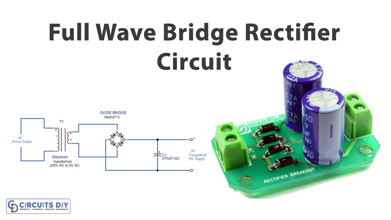
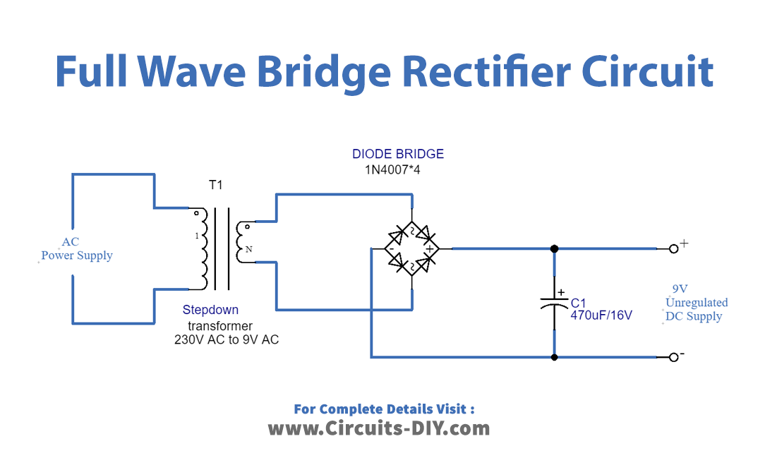
A full-wave bridge rectifying circuit comprises four diodes that are coupled diagonally in a bridge topology. The operation is quite similar to that of a center-tapped transformer. It used both the positive and negative sides of the cycles for rectification in this case. The major difference is that there are two more diodes besides the center-tapped diode, and no center-tapped transformer is employed. The rest of the functionality remains the same.
Hardware Required
| S.no | Component | Value | Qty |
|---|---|---|---|
| 1. | Step Down Transformer | – | 1 |
| 2. | Diode | 1N4007 | 4 |
| 3. | Load | – | 1 |
| 4. | AC Power Supply | – | 1 |
Circuit Diagram
Working Explanation
The Full Wave Bridge Rectifier Circuit first has a step-down transformer in it. The step-down transformer converts high voltage AC to low amplitude AC. There are four diodes in the circuit, connected according to the diagram.
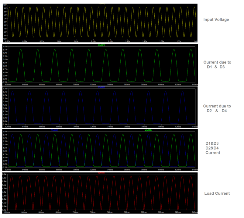
During the positive cycle, terminal A is positive regarding B. The current passes via the D1 diode and RL, then the D3 diode, and ultimately the terminal B. Diodes D2 and D4 are not conducting any current supply during this cycle.
During the negative cycle of the input, terminal B is positive regarding terminal A, and the current now travels via D2, RL, and D4 diodes before reaching terminal A. The diodes D1 and D3 are not conducted throughout this cycle.
Hence, As a result, the circuit becomes conducted in both positive and negative cycles.
Application and Uses
- Power supply.
- Amplifiers.
- Driver circuit.
- Inverters, etc