In this tutorial, we will construct a very entertaining circuit simple FM transmitter circuit. Hence, It is an enjoyable project to create an FM transmitter and broadcast our own signaling. Especially with this circuit, you need not damage your own boost converter or use a mower to set up the circuit correctly. In this tutorial, you will learn how to create your own with artful components and how to work with an FM transmitter.
In the “Circuits for Hobbyists” book (page 75), we adapt the circuit given by Tony Van Roon. This is an impressive sight if you’re looking for some electronics tinkering.
Hardware Component
The following components are required to make FM Transmitter Circuit
| S.no | Component | Value | Qty |
|---|---|---|---|
| 1. | Breadboard | – | 1 |
| 2. | Battery | 9v | 1 |
| 3. | Connecting Wires | – | – |
| 4. | Speakers for testing | – | 1 |
| 5. | Audio Amplifier | LM386 | 1 |
| 6. | 4 Input NAND gate Schmitt Trigger | SN74LS13 | 1 |
| 7. | Audio Jack | 3.5 mm | 1 |
| 8. | Voltage Regulator | 7805 | 1 |
| 9. | Capacitor | 0.1uF, 10uF, 100uF, 1000uF, 22pf | 1, 1, 1, 1, 1 |
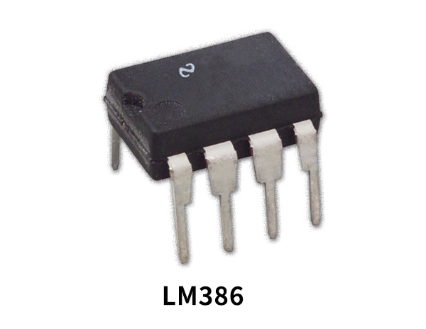
LM386 Pinout
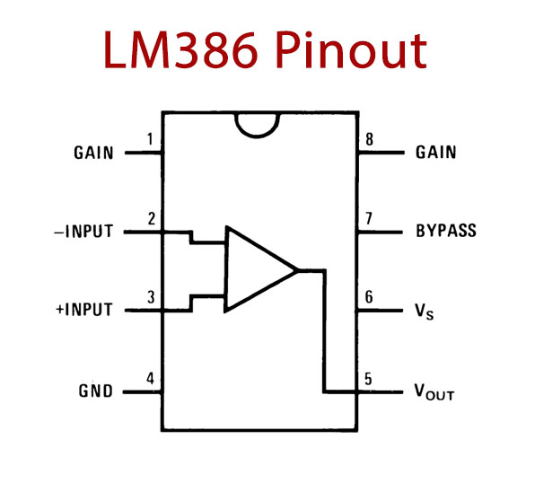
For a detailed description of pinout, dimension features, and specifications download the datasheet of LM386
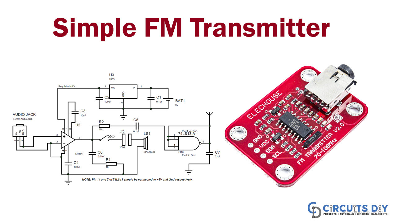
FM Transmitter Circuit
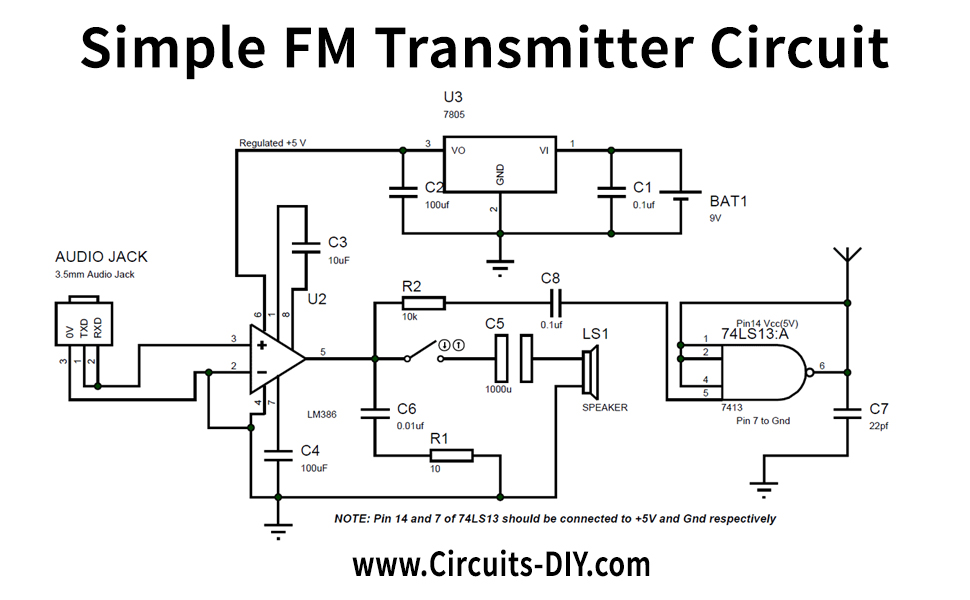
Circuit Operation
It can be built on a panel or displayed on a Perf sheet. A 9V battery is required to power the whole circuit. If you are using a power adapter, guarantee that you install a filter condenser to eradicate harmonic distortions. The circuit’s audio amplification is a preamplifier, amplifying the audio signal from the audio unit and transmitting it to the Oscillating circuit. This IC enhances the audio signal quality.
There should be a conductor and a capacitor in the oscillating circuit. tOur design is developed to oscillate Harmonics at around 100Mhz on a 3rd order, the IC 74LS13, a four-input NAND gate Schmitt Trigger. BesidesOur design is developed to oscillate Harmonics at around 100Mhz on a 3rd order, the IC 74LS13, a four-input NAND gate Schmitt Trigger. In addition, the condenser is very crucial to make it work across the IC power tracks.
Three terminals for connection L, channel R, and ground are situated in the 3.5 mm audio socket. We split the channel pins to the mono channel as shown in the accompanying figure, integrate it to pin 3, and connect the ground to pin 2 of LM386. The Amplifier circuit can indeed be tested with an 8 Ohm commentator. This presenter should be disconnected during circuit adjustment.
Applications and Uses
Furthermore, For transmitting & receiving FM, the FM transmitter uses VHF radio frequencies from 87.5 to 108.0 MHz. With less power, this transmitter improves the network range. Depending on the induction coil, the performance, and the fully operational wireless audio transmitter circuit.