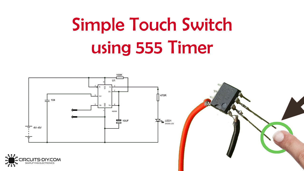
Here in this tutorial, we are going to develop a project for Simple Touch Switch Circuit. This simple touch switch is rendered by using a MONOSTABLE vibrator, the 555 timer IC device. This stable stage is LOW so that after the trigger is disabled, the time production is low.
Essentially we have a LED in this circuit that flips off when we hit a timer pin. For the time the trigger is present, the LED will be ON. The LED shuts off until the trigger has been disabled.

Hardware Components
The following components are required to make the Touch Switch Circuit
| S.no | Component | Value | Qty |
|---|---|---|---|
| 1. | Supply voltage | 4 to 6V | 1 |
| 2. | IC | NE555 Timer | 1 |
| 3. | Resistor | 100K, 470R | 1 |
| 4. | LED | – | 1 |
| 5. | Ceramic Capacitor | 100nF | 1 |
| 6. | Electrolytic Capacitor | 10µF | 1 |
| 7. | Touch plates | – | 1 |
NE555 IC Pinout

For a detailed description of pinout, dimension features, and specifications download the datasheet of 555 Timer
Touch Switch Circuit
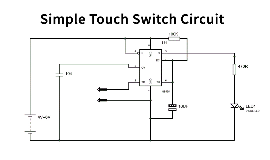
Working Explanation
The figure above shows the Touch Switch circuit diagram. It should not exceed 6 V for the voltage given in this circuit, causing the IC to burn out. If a trigger has been transmitted, the capacitor between pin6 and pin1 decides the LED turns on time.
This circuit can be changed by adjusting the 10uF capacitance to 1000uF one to ON for 2 minutes on a single trigger. With the change in capacitance, several times can be switched on, and hence the circuit can be used as a staircase light.
Applications and Uses
A touch switch is a switch type that only an object needs to be touched. It is used in numerous lamps and wall switches with a metal exterior and on public computer devices. A touchscreen comprises a set of touch buttons on display. The simplest form of the touch sensor is a tactile switch.
Related posts:
 Simple Audio Amplifier Circuit Using 2SC2625 Transistor
 Door Open Alarm Circuit with Hall Effect Sensor
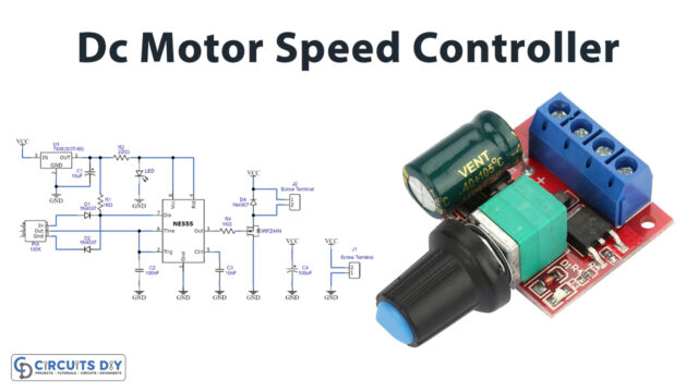 Dc Motor Speed Control Circuit using 555 Timer IC
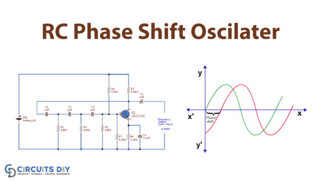 RC Phase Shift Oscillator with 2N2222 Transistor
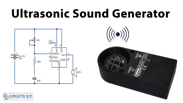 Ultrasonic Sound Generator using 555 Timer
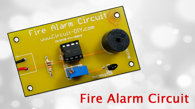 How to Make a Simple Fire Alarm Circuit using LM358 IC - Electronics Projects


