Introduction:
The oscillator as known is a circuit that is used to produce oscillations either sinusoidal or non-sinusoidal at the desired frequency. There are many types of oscillator circuits, RC oscillator is one of its types. The RC oscillator circuit is also known as the phase shift oscillator which produces the sinusoidal signal at its output. It uses the regenerative feedback signal to generate oscillations that are acquired by the RC network in the RC oscillator circuit.
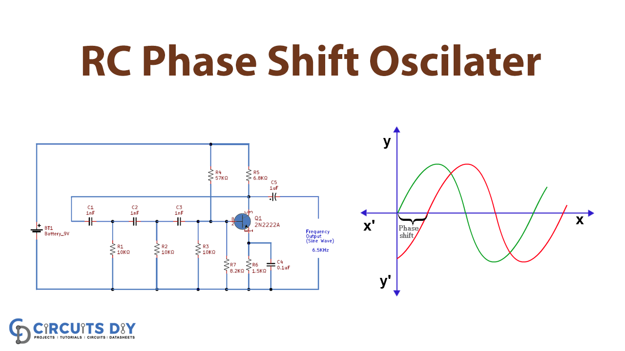
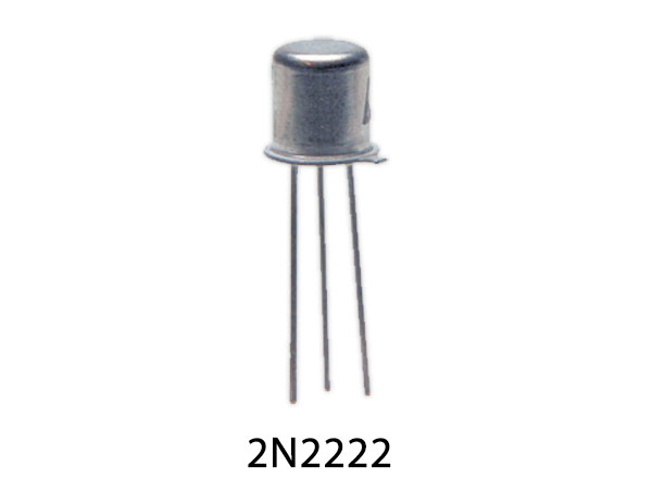
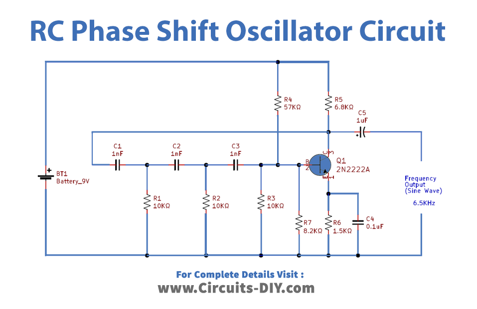
The circuit is designed using a capacitor and resistor to make a network that provides the required phase shift through a feedback signal. This type of oscillator has a good stability of frequency and is useful for a wide range of applications. The RC or phase-shift oscillator uses an NPN transistor 2N2222A and other passive components to generate oscillations at the required frequency range.
This post explains the complete working principle and applications of RC oscillators with a detailed circuit diagram.
Hardware Components
The following components are required to make RC Phase Shift Oscillator Circuit
| S.no | Component | Value | Qty |
|---|---|---|---|
| 1. | Battery | 9V | 1 |
| 2. | Transistor | 2N2222A | 1 |
| 3. | Ceramic Capacitor | 0.1μF, 1nF | 1, 3 |
| 4. | Resistor | 57KΩ, 6.8KΩ, 1.5KΩ, 10K, 8.2KΩ | 1, 1, 1, 3, 1 |
| 5. | Electrolytic Capacitor | 1uF | 1 |
RC Phase Shift Oscillator Circuit
Working Explanation
For this simple circuit, we have used an NPN transistor 2N2222A which is used as a common emitter amplifier while the feedback is obtained from the RC network and the output is acquired at the collector terminal of the transistor which is coupled with a capacitor.
On applying the 9V DC from the battery, the oscillations are produced due to the variations in voltage levels in the power source and the variations in the base current due to the noise variations in the transistor, and these variations are amplified by the transistor.
The RC network is divided into three stages and each stage provides a phase shift of 60° hence a total of 180° phase shift is obtained from the feedback element. Also, the transistor amplifier provides a phase shift of 180° which means a total phase shift of 360° is achieved that provides positive feedback. At the output, a continuous smothered sinusoidal waveform is attained.
RC Phase shift oscillator formula:

The RC phase shift oscillator circuit provides stable oscillations at lower frequencies.
Applications
The applications of RC phase shift oscillator are listed as follows:
- This type of oscillator circuit is applicable for lower frequencies ranging from a few Hz to 200Hz.
- These oscillators are applicable for GPS systems.
- The circuit is used in musical instrument’s sound synthesis.