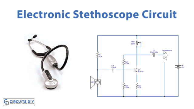
Introduction
For any device or circuit, both over and under voltages are harmful. Under voltages can generate light flickers while overvoltages can damage the whole device. Understand this by the example of motor, a motor may get burned because of low running voltages or because of high voltages. So, we comprehended that both the higher voltages and the lower voltages can do a greater amount of harm to any circuit. Hence, every device needs a voltage protection circuit that can indicate and protect the devices from high or low voltage Thus, there are two types of protection circuits available, under-voltage and overvoltage. Here in this tutorial, we are going to make a “Simple Overvoltage Protection Circuit”
Hardware Required
| S.no | Component | Value | Qty |
|---|---|---|---|
| 1. | Zener Diode | 5.1V | 1 |
| 2. | PNP Transistor | BC557 | 2 |
| 3. | LED | – | 1 |
| 4. | Resistor | 2KΩ, 6.2KΩ, 1KΩ | 1, 1, 1 |
| 5. | 2 Pin Connector | – | 2 |
Circuit Diagram
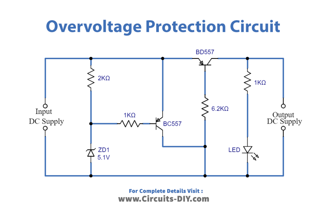
Working Explanation
In this simple overvoltage protection circuit, you first need to select the regulating voltage range of the diode (Zener). After that, connect two BC557 PNP transistors having a specific voltage range. Here transistors are working as a switch. LED is there in the circuit to show the presence of output voltage. So, after applying DC power supply to the circuit, the reverse-biased diode acts as the voltage regulator and regulated voltage flows through transistor Q1 and to the base of transistor Q2. Now, Q2 provides voltage from the input source to load when under 5V. So, if the input source voltage increases more than 5V then Q1 and Q2 become non-conductive.
Application and Uses
- The circuit is used in any high voltage device that needs protection.
- It can be used in automation circuits.
- The circuit breaker is one of its applications.