Introduction
Have you ever wanted to play the bagpipes but found the instrument too complex or expensive to learn? Well, thanks to this easy-to-construct electronic bagpipe circuit, you can enjoy the iconic sounds of bagpipe music without the hassle.
So, get ready to enter a world of pure imagination, where the sounds of a traditional mouth-operated bagpipe instrument are brought to life with the help of an easy-to-build electronic circuit. We bring to you a simple electronic bagpipe circuit that generates an exact replication of the unique dual-tone drone sound!
Hardware Required
You will require the following hardware for the Music Generator Circuit.
| S.no | Components | Value | QTY |
|---|---|---|---|
| 1 | Transistor | 2N2646, 2N3904, 2N3906 | 2, 2, 1 |
| 2 | Capacitor | C1 to C4 = 0.1 Ceramic C5 = 220 Electrolytic | 4 1 |
| 3 | Resistor | R1 to R4 = 100OHM R5 & R6 = 1000OHM R7 to R22 = 3300OHM | 4 2 15 |
| 4 | Diode | D1 to D16 = 1N914 | 16 |
| 5 | Speaker | 8ohm | 1 |
| 6 | Switches | – | 11 |
Circuit Diagram
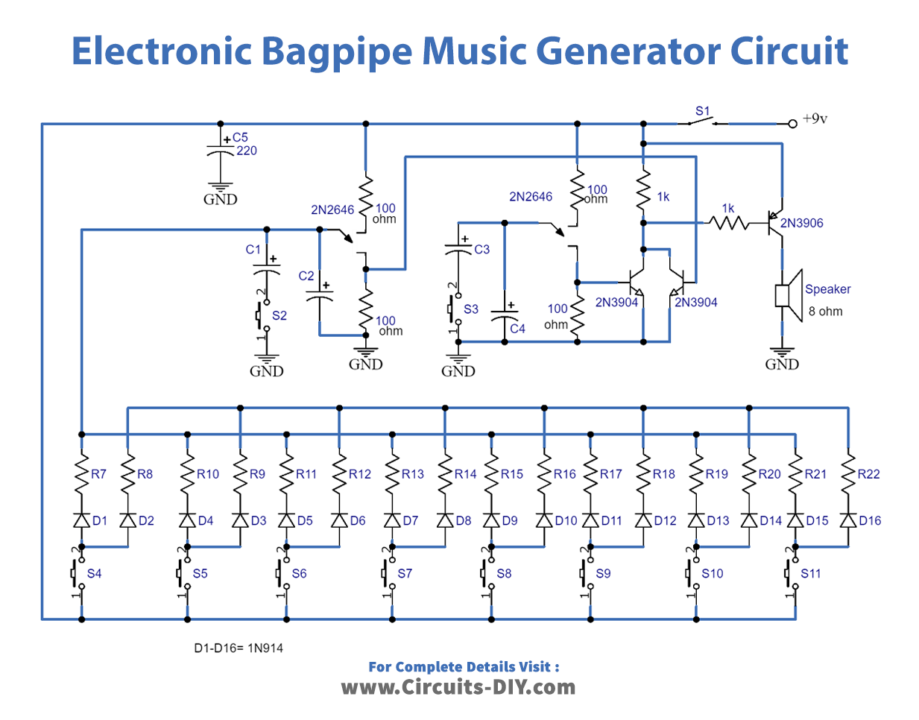
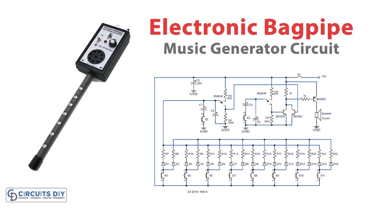
We designed the circuit to replicate the dual-tone drone sound produced by an actual mouth-operated bagpipe. The circuit is made up of a few key components:
- Two unijunction transistors (Q1 and Q2)
- Pushbutton switches (S4 to S11)
- And resistors (R7 to R22).
Construction
Building the electronic bagpipe circuit is easy and can be done on a perf board or PCB. You can enclose it in a plastic or wooden case or create a special enclosure. This will give the circuit a more professional look.
Working Explanation
The electronic bagpipe circuit functions through a simple process. The two unijunction transistors are connected in separate audio oscillator circuits. The frequency of each oscillator is determined by one of the pushbutton switches, which selects one of the two resistors associated with that oscillator.
The odd-numbered resistors, from R7 to R21, set the frequency for the Q1 oscillator circuit, while the even-numbered resistors, from R8 to R22, determine the frequency for the Q2 oscillator circuit. When S4 is pressed, the positive supply is channeled to R7 and R8 via isolation diodes D1 and D2, enabling the pair of oscillators to function. Every cycle of operation produces a thin, fast-rising positive pulse at B1 of both Q1 and Q2.
The next step involves the transistors Q3 and Q4, which act as a standard audio mixer to assimilate the pulses from each oscillator. The mixed signal at the collectors of Q3 and Q4 is attached via R6 to the base of Q5, where the signal gets amplified and powers an 8 Ω speaker, SPKR1.
To produce the dual-tone drone of the bagpipe, resistor values R7 to R22 must be chosen in pairs and in the range of 3.3 k and 33 k. This will determine the oscillator’s operating frequency. You can select the resistors and tune the instrument by hearing or using a frequency counter. The 16 resistors, R7 to R22, can be swapped with miniature trimmer potentiometers to simplify the tuning process.
The circuit includes switches S2 and S3, which reduce the oscillator’s frequency by about one-half when closed. This generates a new set of tones.
Final Words
In summary, this circuit is an excellent way to enjoy the distinctive sounds of bagpipe music without needing an actual bagpipe instrument. With a few essential components, you can build a simple and cost-effective electronic bagpipe. Try this circuit, and for any query, our comment section is there for you. Happy learning!