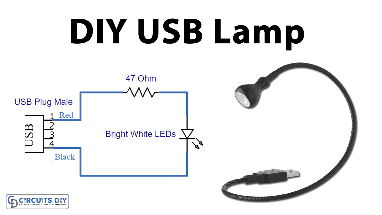
A USB Lamp circuit is a simple electronic circuit that serves the simple purpose of providing emergency light fixtures through the USB port of a Personal Computer or a laptop. In this project, we are going to design a simple USB Lamp Circuit using a Type ‘A’ USB 2.0 plug.
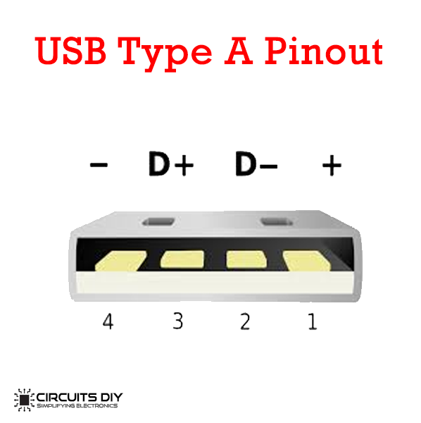
USB Type-A connectors, commonly known as Standard-A connectors, are flat and rectangular. Type A Is the “original” USB connector and is the most recognizable and commonly used plug. USB Type-A connectors are supported in every USB version, including USB 3.0, USB 2.0, and USB 1.1. USB Type ‘A’ connector primarily provides services to host controllers in computers and hubs. USB-A socket is built to provide a downstream connection intended for host controllers and hubs, rarely implemented as an upstream connector on any device.
Hardware Components
The following components are required to make a USB Lamp Circuit
| S.no | Component | Value | Qty |
|---|---|---|---|
| 1. | Breadboard | – | 1 |
| 2. | USB Type ‘A’ Male Plug | – | 1 |
| 3. | LED | 5mm | 1 |
| 4. | Connecting Wires | – | 1 |
| 5. | Resistor | 47 ohms | 1 |
USB Pinout
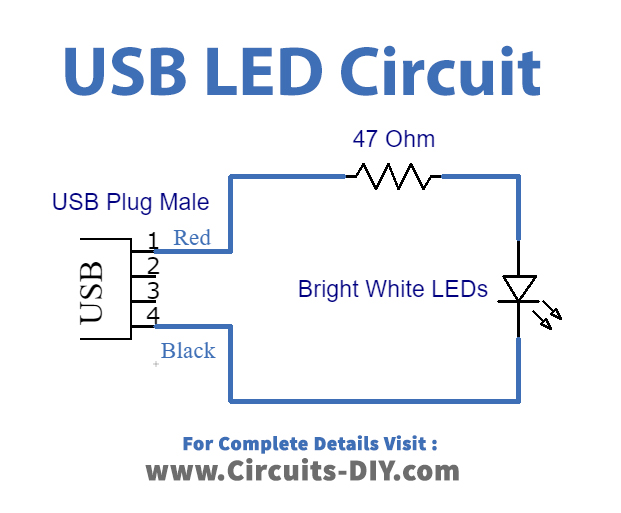
USB Lamp Circuit
Working Explanation
This circuit is pretty simple and uses only a single 47 ohms resistor, LED, and a USB type “A” male plug. The 47 ohms resistor limits the current to 25mA and it is ideal for operating a bright white LED. You can easily connect this circuit to any extra or scrap USB cable you have.
Its intended mode of operation is through a laptop in case of a sudden power outage. It can also be mounted on a mobile USB port to provide quick & easy maintenance in places where it is not practical to bring a bulky emergency light, torch, or flashlights such as crammed-up spaces like a small fuse box or a PC’s backboard.
Applications
- Serves as an emergency lamp for sudden power outages with devices such as laptops & personal computers.
- Relatively cheap and affordable circuit.