Have you heard about the emergency fan circuit? Are you a beginner and are searching to make some different projects that may also give you knowledge of electronic circuits? So, let us make an Emergency FAN Circuit with us. Basically, an emergency fan circuit is a multipurpose circuit. Multipurpose means it contains different other circuits too. For example, it uses a step-down transformer and a full bridge Rectifier made from diodes. It also regulator IC to get the regulated DC voltage. The circuit also contains some other components like a relay. So, if you want to learn about basic electronics, this circuit is for you.
Hardware Required
| S.no | Component | Value | Qty |
|---|---|---|---|
| 1. | Step Down Transformer | 9-0 V AC | 1 |
| 2. | Diode | 1N4007 | 6 |
| 3. | Voltage Regulator IC | LM7809 | 1 |
| 4. | Relay | 9V | 4 |
| 5. | SLA Battery | 6V, 4.5Ah | 2 |
| 6. | Capacitor | 1000μF/16V, 0.01μF | 1, 1 |
| 7. | DC Fan | 9V | 1 |
Circuit Diagram
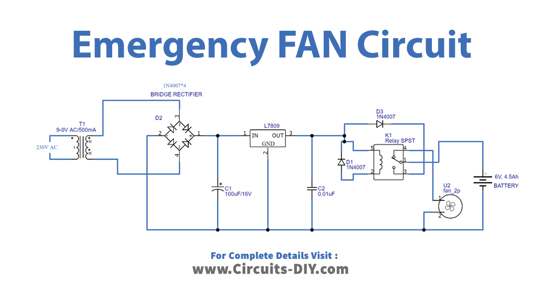
Working Explanation
In this Emergency FAN Circuit, the connected transformer first steps down the voltage which is then given to the bridge rectifier circuit that is made from the diode. The rectifier gives the DC out having some ripples which are then removed by the capacitor C1. This rectified ripple-free output is provided to the IC to regulate. The IC is then connected to the relay coil. Hence, when the supply is there, the relay gets energized and the common terminal makes a connection to the normally open contact. This makes the SLA battery charge. If any power failure happens, the relay coil gets de-energized and the terminal makes a connection with Normally closed contact therefore DC Fan starts rotating
Application and Uses
- It can be used in various industries,
- It may be used in automatic circuits to use for emergency purposes same as emergency lights.