Introduction
Are you ready to feel the rumble and get the ultimate bass experience? Look no further! In this tutorial, you’ll learn how to make a high-power subwoofer amplifier circuit from scratch. With clear step-by-step instructions and illustrations, even beginners can make this circuit.
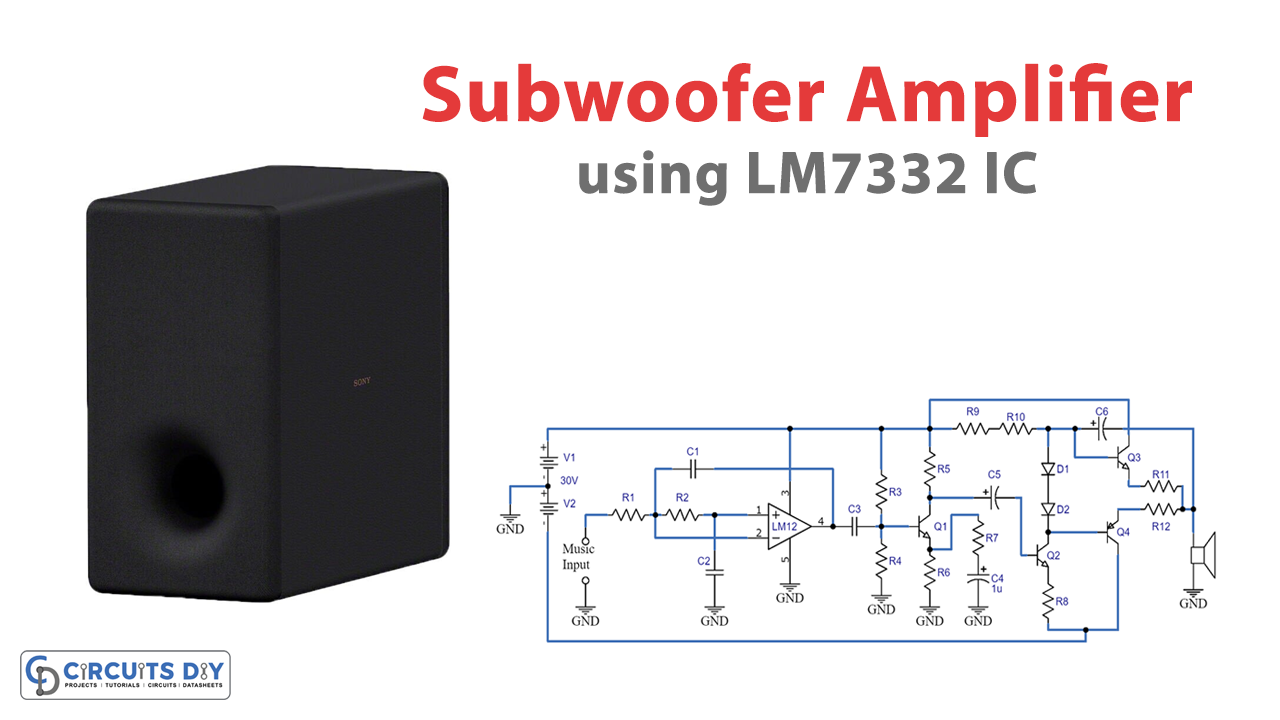
The subwoofer amplifier circuit we will build can deliver high power output to drive even the most demanding subwoofers. This circuit is designed to be efficient and produces minimal distortion, ensuring top-notch sound quality. By the end of this tutorial, you’ll have a deep understanding of the components and their functions, making it easier for you to troubleshoot or make modifications in the future. So let’s get started and bring your music to life with this high-power subwoofer amplifier circuit!
Hardware Required
You will require the following hardware for the Subwoofer Amplifier Circuit.
| S.no | Components | Value | QTY |
|---|---|---|---|
| 1 | IC | LM7332 | 1 |
| 2 | Polar Capacitor | 1uF, 10uF | 1, 3 |
| 3 | Non Polar Capacitor | 0.1uF | 2 |
| 4 | Transistor | 2N222A, TIP41, TIP147 | 1, 2, 1 |
| 5 | Diode | 1N4007 | 2 |
| 6 | Resistor | 5.6k, 120k, 27k, 15k, 3.3k, 330, 33, 2.7k | 2, 1, 1, 1, 1, 1, 1,2 |
| 7 | Battery | +/-30V | 1 |
| 8 | Speaker | – | 1 |
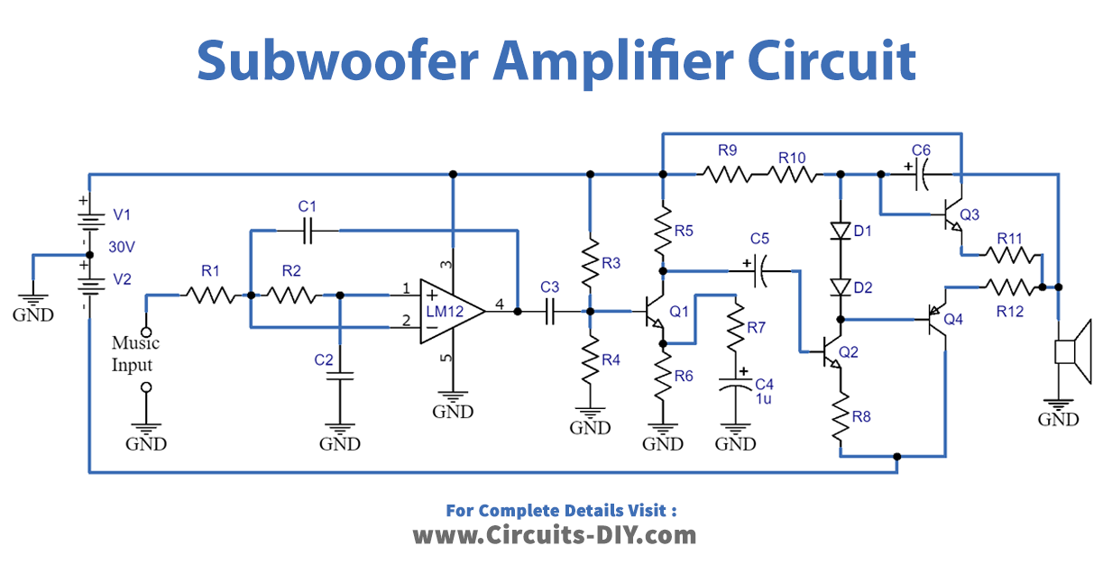
Circuit Diagram
Circuit Explanation
Audio Filter Design
The circuit uses the design of a Sallen Key low-pass filter using the OPAMP LM7332. The filter has a cut-off frequency of 200Hz and a quality factor of 0.707. The values of the capacitors and resistors were calculated based on the given parameters. R1 and R2 are 6K resistors. The filter is designed to have a closed-loop gain, so no resistors are needed in the non-inverting pin.
Pre Amplifier Design
The pre-amplifier is based on the class A operation of transistor 2N222A. A supply voltage of 30V is required to achieve an output power of 100W with a load resistor of 4 Ohms. The values of the resistors and capacitors were calculated based on the transistor’s specifications and the desired circuit parameters.
Power Amplifier Design
The power amplifier is designed using Darlington transistors TIP142 and TIP147 in class AB mode. The biasing diodes were chosen based on their thermal properties and are 1N4007. R9 is a 3K resistor and is used for low-bias current. A driver stage is also included to provide a high-impedance input for the power amplifier. The bootstrap resistor, R10, is 3K and provides a high impedance to the Darlington transistors.
Circuit Operation
The audio signal is filtered through the Sallen Key low-pass filter to remove frequencies above 200Hz. The filtered signal is then amplified by transistor Q1 and converted to a high-impedance signal by transistor Q2. The class AB power amplifier is then used to drive a low-impedance subwoofer (around 4 Ohms). The emitter resistors and diodes reduce distortion and ensure proper operation.
Applications
- It can be used with home theatre systems to operate subwoofers
- Also, Suitable for enhancing low-frequency sound in audio systems
- Moreover, it produces high-power output signals for driving low-impedance loudspeakers or subwoofers.
Final Words
We hope that you found this article informative and helpful. We tried to give a complete picture of the whole process, from getting the necessary components to building the circuit. Hope this information will make the application process smoother and less stressful. If you have any questions or need further clarification, please feel free to ask. Happy learning!