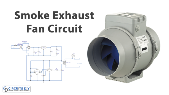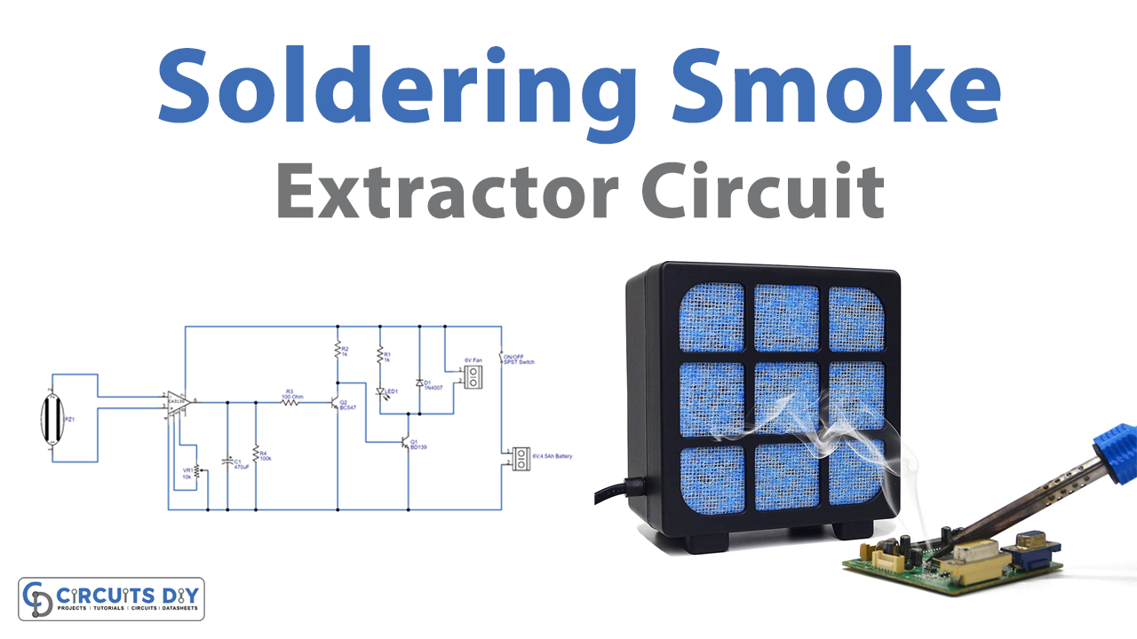
Introduction
We already know how vital it is to protect individuals and property from fire and smoke; thus, the extraction of smoke is a crucial thing. In addition, if you make electronic circuits, you know that when we solder components on, it generates smoke and fumes that are harmful and damaging to human health. To prevent this issue, here is a simple circuit that you can build yourself. So, in this tutorial, we are going to make a “Soldering Smoke Extractor Circuit.”
Smoke extractors are devices designed to effectively remove smoke, heat, and combustion products from areas affected by smoke. This small smoke detector circuit that we are making is useful while soldering. The circuit requires very few basic components that are easily available.
Hardware Required
| S.no | Component | Value | Qty |
|---|---|---|---|
| 1. | Amplifier | CA3130 | 1 |
| 2. | Transistor | BC547 | 1 |
| 3. | Transistor | BD139 | 2 |
| 4. | Red LED | – | 1 |
| 5. | Switch | – | 1 |
| 6. | Potentiometer | 10KΩ | 1 |
| 7. | Capacitor | 470uF | 1 |
| 8. | Resister | 100Ω, 1KΩ, 100KΩ | 1,2,1 |
| 9. | 2-Pin Connector | – | 2 |
Circuit Diagram
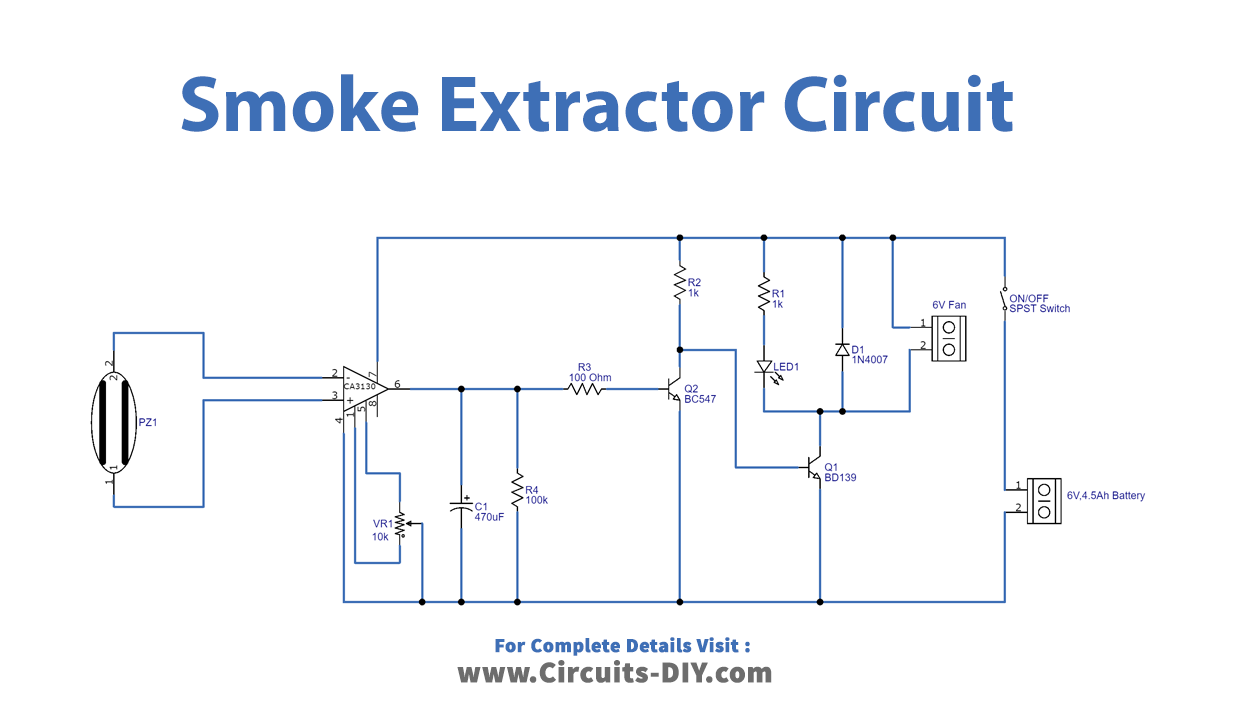
Working Explanation
In this Smoke Extractor Circuit, a DC fan serves as a smoke and fumes exhaust device, and it only operates when we solder components; a 6V 4.5 Ah rechargeable battery is utilized to provide bias. The piezo element is connected to the inverting and non-inverting terminals of the opamp CA3130, potentiometer VR1 is used to vary the offset, and the output from the operational amplifier is connected to the transistor Q2 BC547 and directed to the BD139 bi-junction transistor, and then an output indicator LED and a 6V fan are connected to the collector terminal of the BD139, which is followed by +Vcc.
Application and Uses
- You can use this circuit while soldering any components on PCB, etc.