Introduction
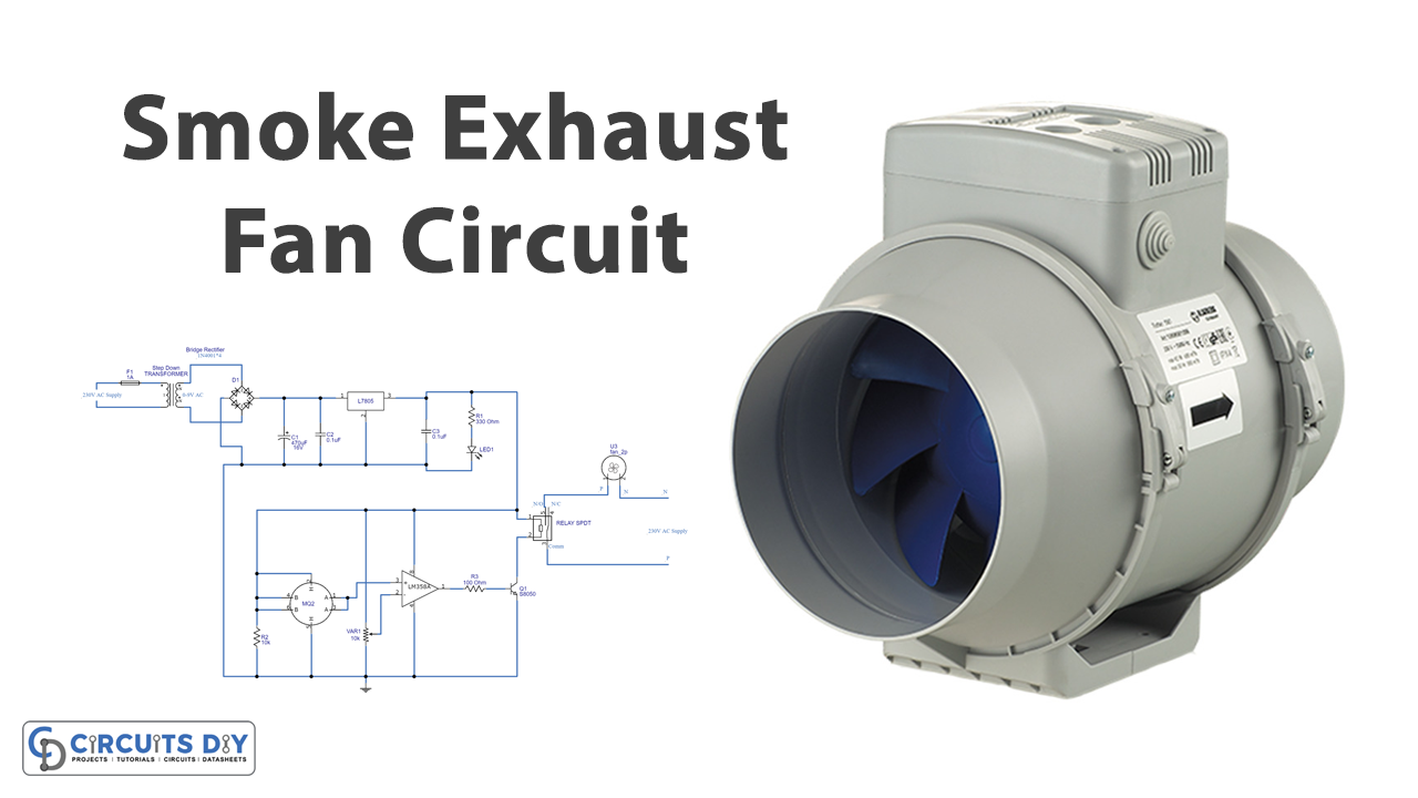
In this tutorial, we will make an “Automatic Smoke Exhaust Fan Circuit”. An automated exhaust system, also known as an auto exhaust fan controller, is circuitry that uses smoke sensors and other electronic components to detect and expel different gases and smoke. Here we are using an MQ2 sensor for this purpose.
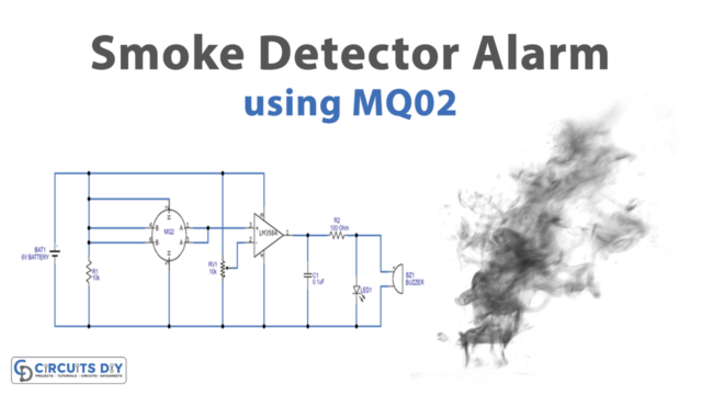
Winsen’s MQ-2 is smoke and combustible gas sensor. It has a detection range of 300 – 10000ppm for combustible gas. The sensing material is SNO2, which has a reduced conductivity in clean conditions and a higher conductivity when there is smoke or combustible gas present. A simple circuit makes monitoring the change in conductivity and converting it to data very straightforward.
Hardware Components
The following components are required to make Smoke Exhaust Fan Circuit
| S.no | Component | Value | Qty |
|---|---|---|---|
| 1. | Stepdown Transformer | – | 1 |
| 2. | Bride Rectifier Diode | 1N4007 | 1 |
| 3. | Relay | 5v | 1 |
| 4. | IC | 7805 | 1 |
| 5. | IC | LM358 | 1 |
| 6. | Transistor | S8050 | 1 |
| 7. | Potentiometer | 10K | 1 |
| 8. | Exhaust Fan | – | 1 |
| 9. | Smoke Sensor | MQ-2 | 1 |
| 10. | Electrolysis Capacitor | 470uf | 1 |
| 11. | Ceramic Capacitor | 0.1uf | 2 |
| 12. | Resistor | 10K Ohm, 330 Ohm, 100Ohm | 1,1,1 |
LM358 Pinout

For a detailed description of pinout, dimension features, and specifications download the datasheet of LM358
7805 Pinout
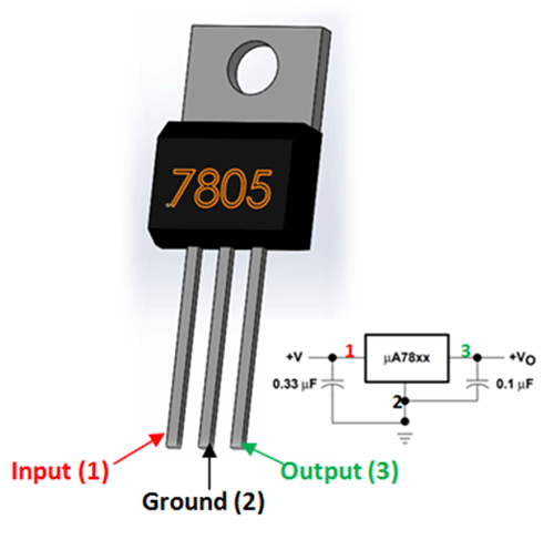
For a detailed description of pinout, dimension features, and specifications download the datasheet of 7805
Smoke Exhaust Fan Circuit
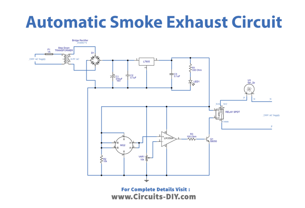
Working Explanation
This Automatic Smoke Exhaust Fan Circuit first uses the transformer which steps down the 220V AC into 9V AC. After that, there is a bridge rectifier that converts the AC voltage into DC. But, this DC voltage has ripples in it, which are removed by capacitors C1 and C2. Then there is a voltage regulator IC that provides regulated Dc voltage at its output pin 3. Here LED 1 shows the status of the power supply. Now, the circuit has a smoke sensor in it. Sensor pins B, H, and B are frequently linked to a +5V supply, as is the SPDT relay coil. The non-inverting input of the operational amplifier is coupled to two sensor terminals A, A. H is another grounded heater terminal. The potentiometer is connected between the +5V DC supply and the variable terminal of the inverting opam’s input. The output of the op-amp is linked to the base terminal of the switching transistor Q1, which functions as a switch in the relay coil terminal.
When there is no smoke, the op-amp output is near 0 volts, and Q1 is cut off mode, preventing ground supply to the relay coil. If the smoke level rises to 4 volts, the op-amp output rises to 4 volts, and Q1 enters the closed turn-on or active state, allowing the relay coil to receive ground current and become an electromagnet. When the coil of the relay gets energized, it draws the common lever to a typically open contact, through which the supply flows, and the exhaust fan is immediately activated. After that, the fan will turn off on its own.
Application and Uses
- Smoke ventilation systems.
- Smoke control devices.
- The circuit can be utilized in kitchens.