In this tutorial, we are going to make a “Simple Smoke Detector Alarm Circuit using MQ02”.
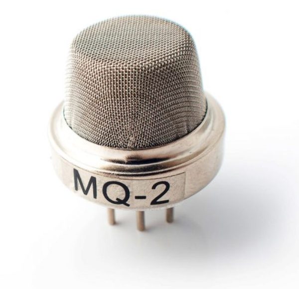
Nowadays a smoke detector becomes an essential system when it comes to maintaining safety precautions for any place, like having a smoke detector installed makes life easy to save you from any fire destruction. Smoke detectors are mainly of two different types ionization smoke detectors and photoelectric or optical smoke detectors. We design a simple smoke detector alarm circuit using MQ02 with a few easily available components. Here gas sensor MQ-02 is the main part of this circuit, it is an ionization smoke detector that is capable of detecting smoke, LPG, propane, hydrogen, and other combustible gases. When there is any sign of smoke in the air, this smoke detector circuit will produce a visible and audible alert.
Hardware Components
The following components are required to make a Smoke Detector Alarm Circuit
| S.no | Component | Value | Qty |
|---|---|---|---|
| 1. | Gas Sensor | MQ-2 | 1 |
| 2. | IC | LM358 | 1 |
| 3. | Resistor | 10KΩ, 100Ω | 1,1 |
| 4. | Variable Resistor | 10KΩ | 1 |
| 5. | Ceramic Capacitor | 0.1µF | 1 |
| 6. | LED | – | 1 |
| 7. | Buzzer | – | 1 |
| 8. | Connecting Wires | – | – |
| 9. | Battery | 6V | 1 |
LM358 Pinout

For a detailed description of pinout, dimension features, and specifications download the datasheet of LM358
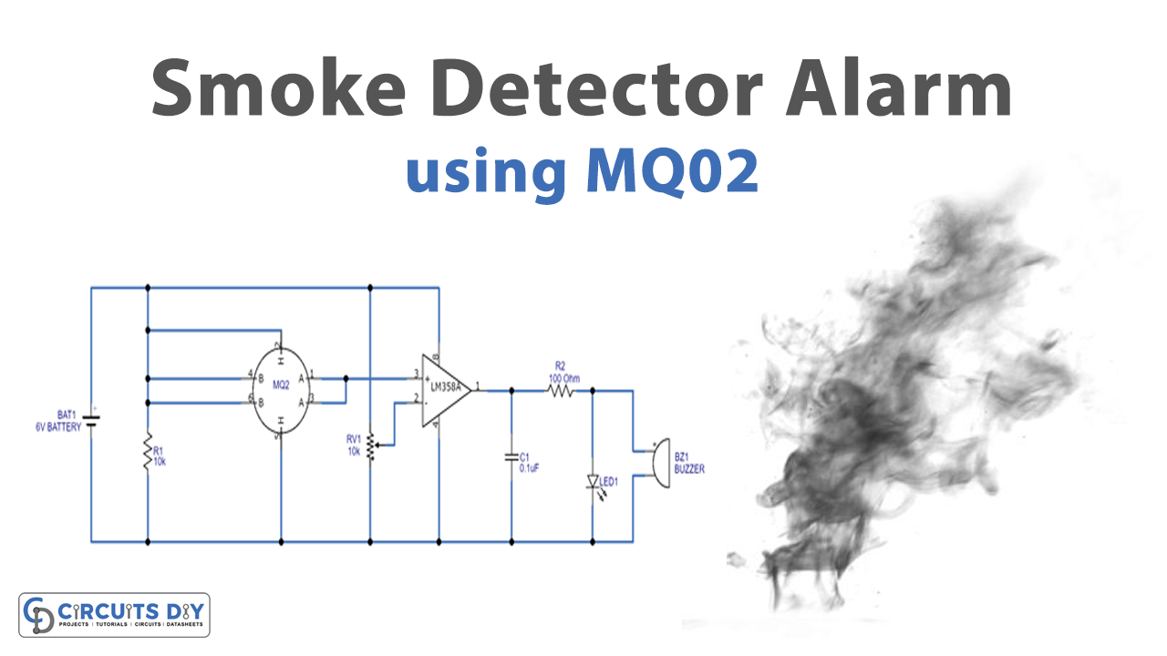
Smoke Detector Alarm Circuit

Working Explanation
As shown in the circuit we have used an LM358 operational amplifier and MQ-2 smoke sensor. The non-inverted terminal of LM358 is interfaced with the smoke sensor’s output, in the gas sensor MQ-02 combines B1, B2, and HB terminals and connects with the bias terminal then combines A1, A2 terminals and connects to the non-inverting terminal of the operational amplifier. Connect HA to the negative bias terminal. The variable resistor is connected between the positive and negative terminal of bias and the variable terminal is connected to the inverting terminal of an operational amplifier. LM358’s inverted terminal is interfaced with POT to adjust the sensitivity of the circuit. Hence, we can change the sensitivity by varying the value of RV1. The amplifier output is connected with the LED and Buzzer.
When there is no smoke in the air, the conductivity between the sensor electrodes remains less because of the resistance order working on 50KW. So the value of the input of the inverting terminal remains higher than the input of the non-inverted terminal, which keeps the LED in an OFF state.
when the smoke is detected by the MQ-02 sensor it means there is heavy smoke because of fire, the sensor gets filled with the smoke and the resistance of the sensor drops to 5KW, which increases the conductivity between the electrodes. This process enables high input of the op-amp non-inverted terminal resulting in high output. With this situation, LED and Buzzer start to indicate and alert.
Applications
It can be used in different types of applications where smoke and other mentioned gas leak detection is required.