An H bridge is an electrical circuit that changes the polarity of an applied voltage to a charge. These circuits are often used in robotics and other applications to allow DC motors to run in or out.
In the beginning, turning a motor can seem like a simple job – just connect the motor to the correct voltage rail and start spinning. But this is not the best way to drive a motor particularly when the circuit has other components involved. Here we will address one of the most commonly utilized and effective methods of running DC motors-H-Bridge circuits.
Hardware Components
The following components are required to make H-Bridge Motor Driver Circuit
| S.no | Component | Value | Qty |
|---|---|---|---|
| 1. | Resistors | 10K, 1K | 2,1 |
| 2. | Potentiometer | 10K | 1 |
| 3. | Capacitors | 100nF, 10uF, 4.7uF | 3,3,2 |
| 4. | SPDT Switch | – | 1 |
| 5. | Diodes | 1N4148 | 2 |
| 6. | Gate driver | TC4427 | 1 |
| 7. | IC | NE555 Timer | 1 |
| 8. | MOSFETs | IRF5210, IRF3205 | 2, 2 |
| 9. | DC motor | – | 1 |
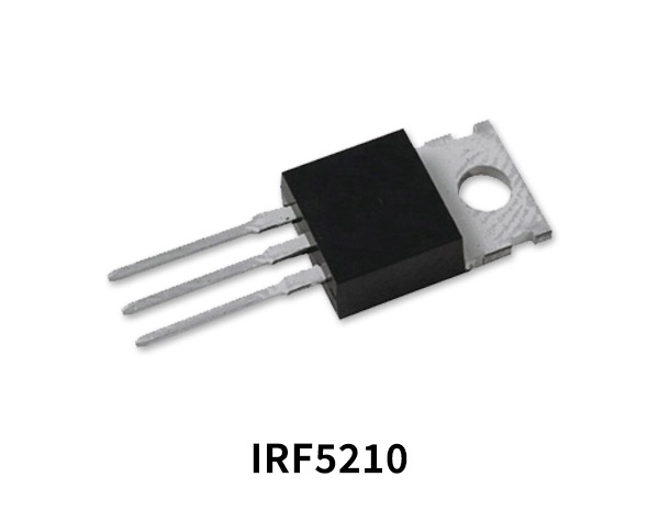
IRF5210 Pinout
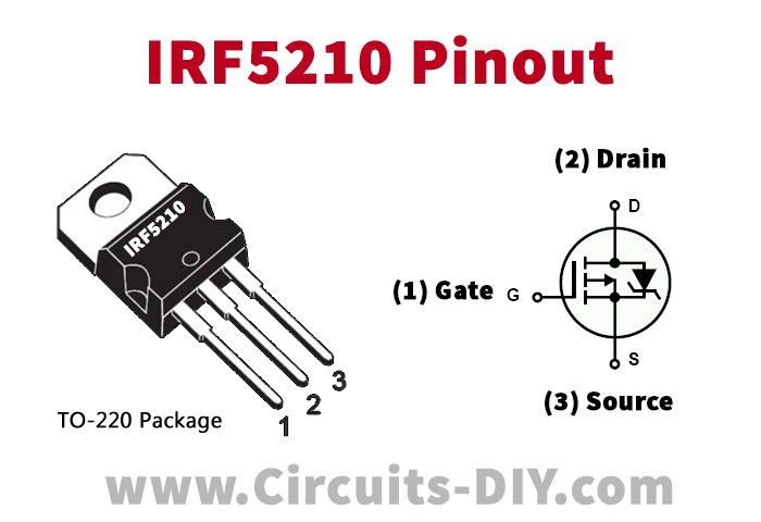
For a detailed description of pinout, dimension features, and specifications download the datasheet of IRF5210
IRF3205 Pinout
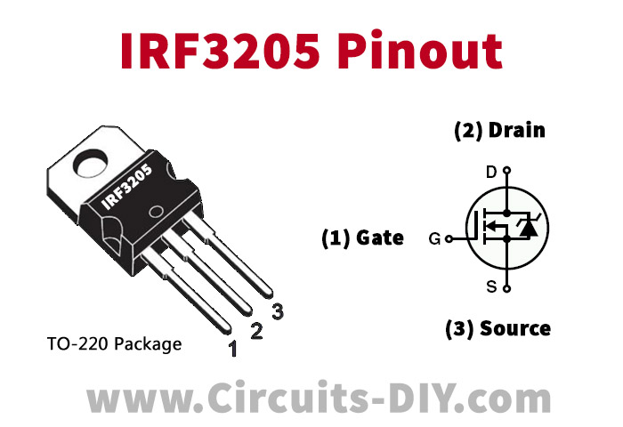
For a detailed description of pinout, dimension features, and specifications download the datasheet of IRF3205
H-Bridge Motor Driver Circuit
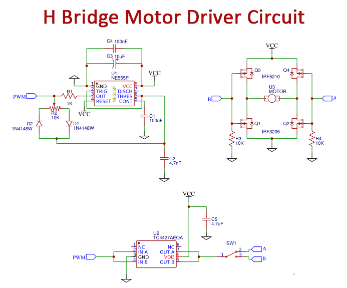
Working Explanation
The timer is a simple 555 circuit producing a duty cycle from about 10 % to 90%. The frequency is set through R1, R2, and C2. Potentiometer R2 controls the duty cycle. The gate driver is a two-channel regular TC4427, with a 1.5A sink/source per line. Here, for further driving current the two channels were parallel. if the frequency is higher the gate driver has to be stronger. The SPDT switch is used to choose the H-bridge leg that controls the path. H-Bridge is the circuit’s functioning component, which controls the motor.
The pulldown resistor usually pulls the MOSFET gates down low. This triggers each of the P-channel MOSFETs to turn on, but this is not a concern because no current will run. When the PWM signal is applied to the one-legged gates, the N and P-channel MOSFETs are alternately turned on and off, controlling the power.
Application and Uses
- It changes the polarity of an applied voltage to a charge.