Introduction
To obtain the particular frequency and amplitude in various electronic circuits, oscillator circuits become part of those circuits. Thus it plays a crucial role in different microcontroller applications. There are also classifications in oscillators that include linear oscillators and non-linear oscillators, Hartley oscillators, Armstrong oscillators, negative resistance oscillators, Colpitts Oscillator circuits, etc. In this tutorial, we are going to the “Hartley oscillator Circuit”. But before making the circuit let us briefly discuss this type of oscillator.
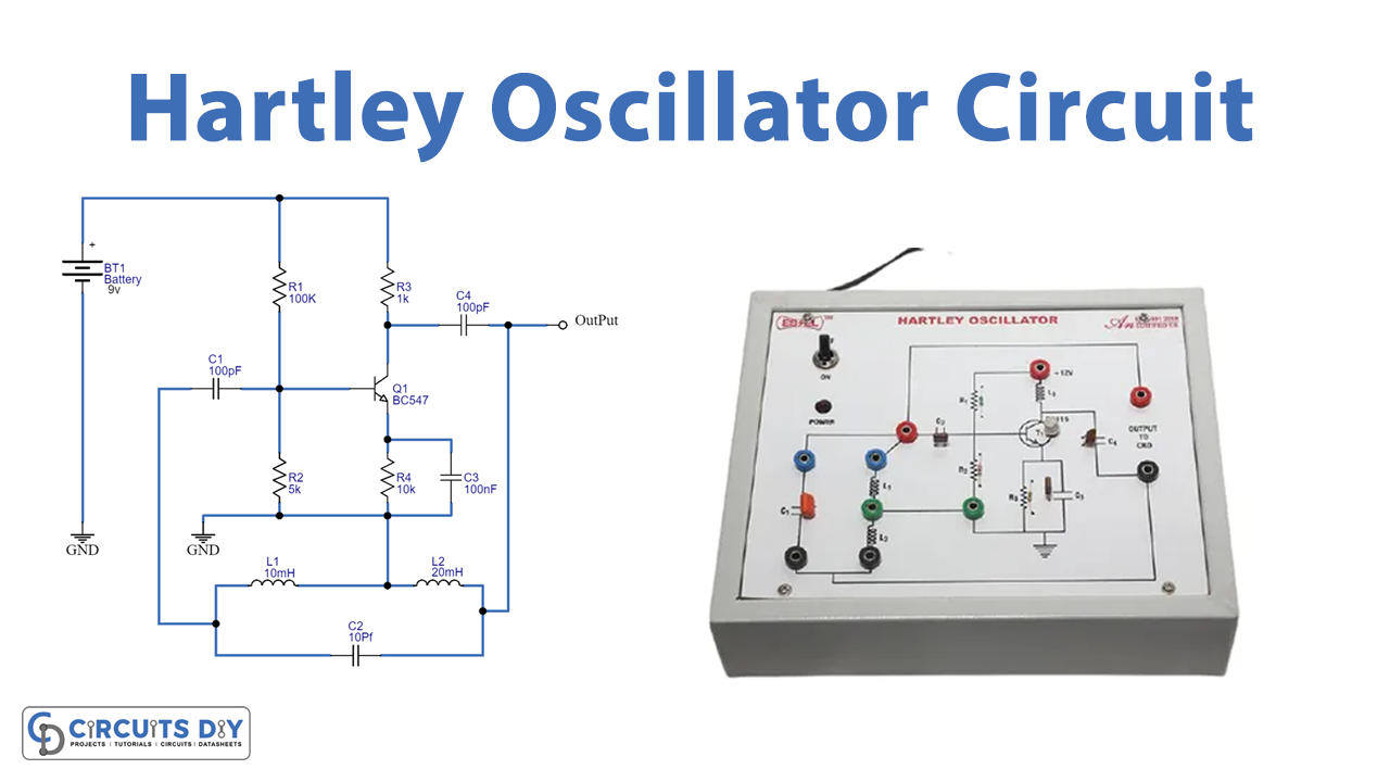
Hartley Oscillators
We frequently know the Hartley circuit as a split-inductance oscillator since loop L is center tapped. Basically, inductance L behaves like two separate coils in extremely nearness with the current running through the coil. We can create a Hartley Oscillator circuit using any setup that utilizes either an only tapped coil like an autotransformer or two coils wired with a single capacitor as displayed in our circuit diagram.
Hardware Required
| S.no | Component | Value | Qty |
|---|---|---|---|
| 1. | NPN Transistor | BC547 | 1 |
| 2. | Inductor | 10mH, 20mH | 1, 1 |
| 3. | Capacitors | 10pF, 100nF, 100pF | 1, 1, 2 |
| 4. | Resistor | 100KΩ, 5KΩ, 1KΩ, 10KΩ | 1, 1, 1, 1 |
| 5. | 2-Pin Connector | – | 1 |
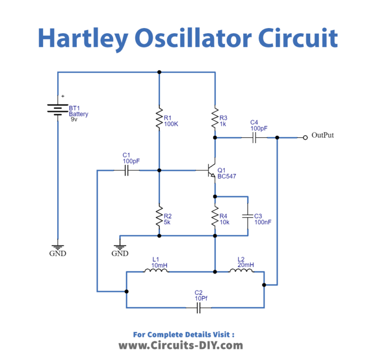
Circuit Diagram
Working Explanation
The Hartley Oscillator Circuit comprises an RC coupled amplifier with a common-emitter configuration transistor. It also includes the tank or tunes circuit having inductors and a capacitor. In the Hartley Oscillator, we connect the tank circuit between the collector and the base of a transistor amplifier. As far as the oscillatory voltage, we connect the emitter to a tapping point on the tuned circuit coil.
When the circuit oscillates, the collector voltage, relative to the emitter, is 180 degrees out of phase with the base relative to the emitter. Moreover, at frequency oscillation, the decrease of base voltage causes an increase in collector voltage. You can say that there is 180 degrees phase shift between the base and the collector of the transistor.
The tapping point plays a crucial role. If you move this near the collector, the feedback increases, however, the output between the earth and collector gets reduced. Thus, the feedback of this oscillator depends on the tapping point. The oscillator generates the output amplitude which remains constant over an entire frequency range.
Application and Uses
- To generate sinusoidal signals with very high frequencies.
- Mobile and radio communication applications.
- Radiofrequency applications, up to 300MHz
- We prefer this oscillator in conditions where it should withstand high and low temperatures frequently.
- Applications where a wide range of frequencies are involved.