In this tutorial, we are going to make a “CD4511 7-Segment Decoder Circuit”.
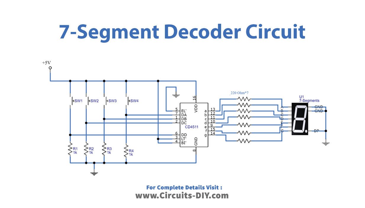
A seven-segment display is a component with seven Light-Emitting Diodes (LED), seven-segment display driver turns on the correct segments of a seven-segment display according to an input. It is widely used to project numbers in many applications. Here we design a simple driver circuit to convert BCD to a 7-Segment display by using CD4511. The CD4511 is a BCD-to-7-segment latch decoder driver constructed with CMOS logic and n-p-n bipolar transistor output devices on a single monolithic structure. It can drive a common cathode seven-segment display. It takes a number in binary form as an input, then displays this number on a 7-segment display using its outputs. Here push button switches are taken as input and a single-digit seven-segment display is being driven by IC CD4511 according to the BCD input from Pushbuttons. By turning on different combinations of the LEDs, a number between 0 and 9 is displayed.
Hardware Required
| S.no | Component | Value | Qty |
|---|---|---|---|
| 1. | 7-Segment display | – | 1 |
| 2. | IC | CD4511 | 1 |
| 3. | Push Button Switch | – | 4 |
| 4. | Resistor | 1K, 220Ω | 4, 7 |
| 5. | Battery | 5v | – |
Circuit Diagram
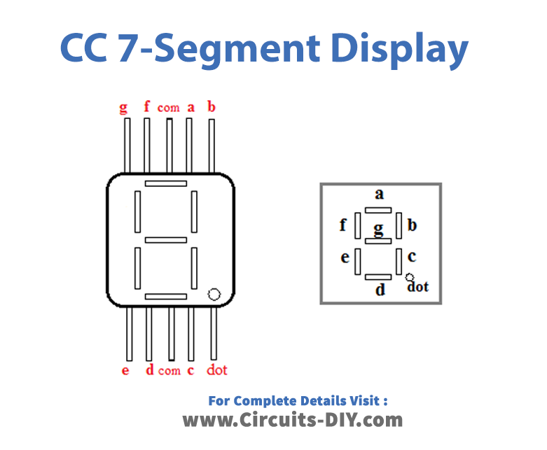
CC 7-Segment Display
Working Explanation
There are four push-buttons, place these switches between biases through the resistor. It will act as BCD logic input to the seven-segment driver IC. Here connect A, B, C, and D (DA to DD) to the corresponding BCD logic input push-button. Now connect seven segment display output from CD4511 to the CC 7-segment display Qa – a to Qg – g and connect DP to the ground because this circuit has only one digit. Finally, connect the Common cathode (CK) pin to Gnd and apply bias to Circuit.
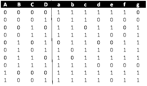
As 7segment displays are among the simplest display units to display numbers and characters. It consists of 8 LEDs, each LED is used to illuminate one segment of the unit, and the 8th LED is used to illuminate a dot in the 7-segment display, these 7 lines (segment) in the unit are used to display a number/character. There are 10 pins, of which 8 pins are used to refer to a,b,c,d,e,f,g, and h/dp, the two middle pins are the common anode/cathode of all the LEDs. These common anode/cathodes are internally shorted so we need to connect only one COM pin. Pressing any button will give a high input to the corresponding pin of 4511 and accordingly decimal numbers will be displayed on the 7-segment. You can show a decimal number from 0 to 9 on a single 7-segment display. Initially, the display will show Zero, as buttons are connected to pull-down resistors and give LOW as output when no button is pressed. According to the truth table logic 1 represents segment LED glowing and Logic 0 represents segment LED OFF condition. Hence for the BCD four-digit input, seven-segments LED shows corresponding Numbers. So, for any particular decimal number, you just follow the table and you will get to know 4 which buttons you have to press for displaying the particular number.
CC 7-Segment Truth table
Applications
They are most commonly used in electronic devices like digital clocks, timers, and calculators to display numeric information.