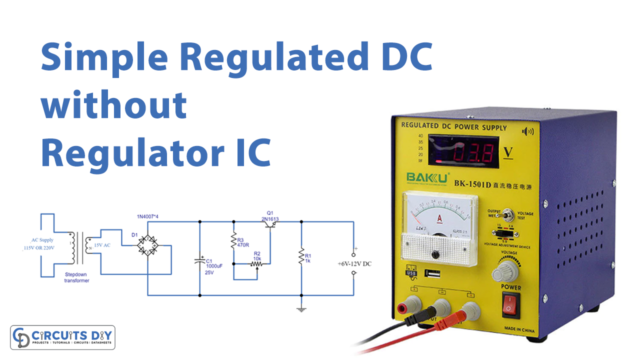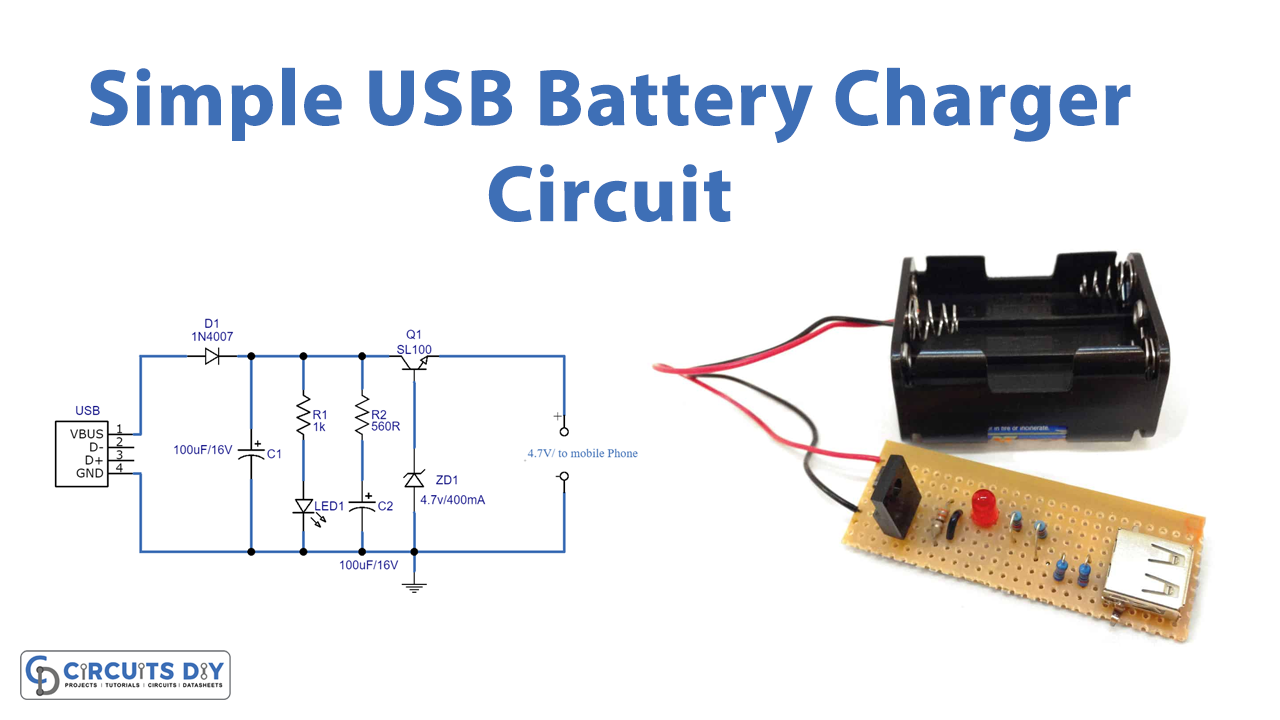
Introduction
We have gotten increasingly reliant on technological devices and gadgets these days. We are just unable to live without them, from cell phones to earphones we can’t live without them. However, these gadgets, can’t operate without their batteries. Batteries need chargers and chargers are of different types. So, in this tutorial, we are going to make a “Simple USB battery charger circuit”.
Because many electronics utilize rechargeable batteries, it is increasingly popular to create a charging circuit that uses the USB port’s power source to charge the rechargeable battery. This feature will make gadgets more comfortable for consumers because they will be powered by the bus and will not require an extra socket or cords. The following circuit requires very few electronic components which are also easily available in the market.
Hardware Required
| S.no | Component | Value | Qty |
|---|---|---|---|
| 1. | Transistor | SL100 | 1 |
| 2. | Zener diode | 4.7V | 1 |
| 3. | Diode | 1N4007 | 1 |
| 4. | USB | – | 1 |
| 5. | LED | – | 1 |
| 6. | Capacitor | 100uF | 2 |
| 7. | Resistor | 1KΩ, 560Ω | 1, 1 |
Circuit Diagram
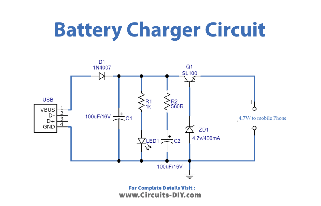
Working Explanation
The Zener diode and switching transistor SL100 were used to build the USB power mobile charger circuit. The USB port provides DC bias to the power supply, which is controlled by a Zener diode based on the regulating voltage range. Choose the Zener diode based on the specifications and requirements of the mobile battery; the output pin provides controlled power. On the output side you get the 4.7V to charge the battery; connect your mobile phone to charge its battery.
Application and Uses
- To charge electronic equipment, devices, and gadgets like mobile phones, etc.