Introduction
Are you tired of the same old dull doorbell chime sound? Want to add a little flair to your home’s entrance? Look no further than a two-tone chime circuit! This circuit allows you to create a unique, customizable chime sound that will impress your guests and set your home apart. Not only is it fun to design and build, but it’s also a great way to learn about electronics and circuit design.
Building a two-tone chime circuit is a relatively simple process and can be completed with just a few essential electronic components. So, roll up your sleeves and get ready to build your own custom doorbell chime sound that will be the talk of the town!
What is a Two-Tone Chime Circuit?
A Two-Tone Chime Circuit is an electronic circuit that produces two distinct tones, typically a high and a low tone when activated. The circuit is often used in doorbells, telephones, and other devices that require the ability to produce different tones for different purposes. The circuit typically consists of an oscillator, tone-generating components, and a switch or other activating mechanism.
Components Required
You will require the following hardware for the Two-Tone Chime Circuit.
| Components | Value / Model | Qty |
|---|---|---|
| IC 1 | (N1…N4) 4093 IC | 1 |
| IC 2 | LM386 | 1 |
| Transistor | BC547 | 6 |
| Diode | 1N4148, AA119 | 3, 2 |
| Resistor | 10Ω, 2m2Ω, 10kΩ, 120kΩ, 47kΩ, 100kΩ, 4k7Ω, 470Ω, 25kΩ, 22Ω | 1, 2, 6, 2, 2, 1, 1, 1, 1, 1 |
| Variable Resistor | 100kΩ | 3 |
| Polar Capacitor | 47uF, 100uF, 220uF | 1, 1, 3 |
| Non-Polar Capacitor | 100n, 330n, 470n, 220n | 3, 1, 1, 1 |
| Switch | 250mA | 1 |
| Speaker | 4.6 / 0.5W | 1 |
| Button | – | 1 |
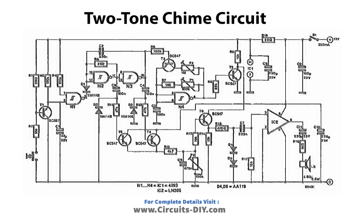
Follow the given circuit diagram and connections to build the Two-Tone Chime Circuit.
Circuit Diagram
Connections
- S2 is connected to T1 using R2, which became the input of NAND gate N1.
- The output of NAND gate N1 controls the oscillator, which comprises N2 and N3.
- The oscillator provides 1Hz pulses to C4, C5, and a second oscillator section (comprising N4 and related parts via R6).
- The output of NAND gate N3 is connected to the input of inverter N4.
- The output of inverter N4 is connected to the input of NPN transistor T3.
- The output of NPN transistor T3 is connected to the collector of NPN transistor T6.
- The emitter of NPN transistor T6 is connected to the input of the AF output amplifier LM386.
- The output of AF output amplifier LM386 is connected to the speaker.
- A buffer capacitor C1 is connected between NAND gate N1 and the oscillator to keep the oscillator running after S2 is released.
- Preset P1 and P2 are connected to control the tone frequencies of the chime sound.
- Preset P3 is connected to control the decay characteristics of the chime sound.
Working Explanation
The circuit tone bell chime is built with inexpensive parts and is easy to construct. When the doorbell button, S2, is pressed, it sends a logic low level to NAND gate N1. This causes N1 to return a high logic level, which switches the oscillator (comprising N2 and N3) around 1 Hz. The buffer capacitor C1 keeps the oscillator running after S2 is released, providing 1 Hz pulses to C4, C5, and a second oscillator section (comprising N4 and related parts via R6).
At inverter N3, a logic high level allows T2 to connect to preset P2 and the frequency-determining parts R7 to P1. Depending on the desired sound, the twin overlapping frequencies can be adjusted with P1 and P2.
The 1 Hz pulses also dictate the packet shape of the chime sound through T4 to T5 and related components. Preset P3 sets the decay characteristics for the two-tone chime sound. T6 acts as a simple voltage-controlled amplifier that powers the single-chip AF output amplifier LM386.
Final Words
This article discussed a two-tone bell chime circuit that can be used as a doorbell. The circuit is easy to construct and uses inexpensive parts. We hope you found this article informative and that it has provided you with a better understanding of how this circuit works. If you have any questions or comments, please feel free to reach out!