Introduction
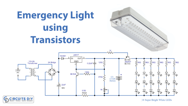
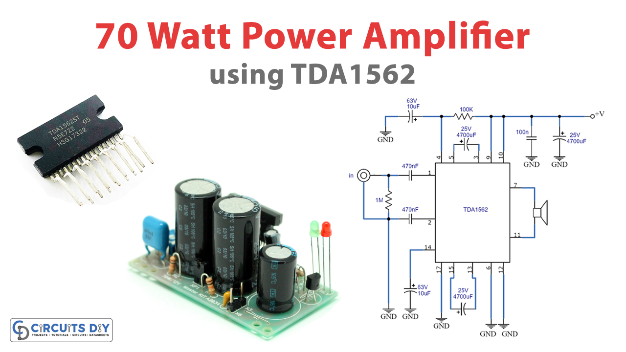
This guide will show you how to make a 70-watt high-efficiency power amplifier circuit using IC TDA1562. This compact and efficient circuit is perfect for amplifying your favorite tunes. Using the TDA1562 IC, this circuit packs a punch and delivers high-quality sound that will fill your room with rich and powerful audio.
But, this power amplifier circuit isn’t just loud; it’s also incredibly efficient. The TDA1562 IC provides high efficiency and low distortion, ensuring that your music sounds exactly as it was intended. Whether you’re a music aficionado, a movie buff, or just someone who wants to crank up the volume, this 70-watt power amplifier circuit is the perfect solution. So, grab your tools and get ready to make some noise!
Hardware Required
You will require the following hardware for High-Efficiency Power Amplifier Circuit.
| S.no | Components | Value | QTY |
|---|---|---|---|
| 1 | IC | TDA1562 | 1 |
| 2 | Polar Capacitor | 10uF, 4700uF, | 2, 3 |
| 3 | Non Polar Capacitor | 100nF, 470nF | 1, 2 |
| 4 | Resistor | 100k, 1M | 1, 1 |
| 5 | Speaker | – | 1 |
Circuit Diagram
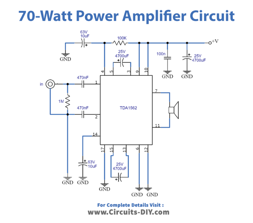
Explanation of Circuit
The TDA1562Q is a mono class-H BTL output power amplifier designed to produce high output power with increased efficiency. The functional description of the circuit includes details on its power output, mode select input, status IIO input, output, diagnostic output, short-circuit protection, temperature recognition, and load detection.
Output Power
The TDA1562Q can produce 70W of output power, but it works like a typical BTL amplifier when lower output power (approximately 18W) is required. If a more significant output voltage swing is necessary, the internal supply voltage will be elevated using external electrolytic capacitors. This results in a significant decrease in dissipation when compared to a class-B output amplifier using the same output power. The heatsink must be suitable for use with audio signals, and if the case temperature exceeds 120C, the IC may switch back to class-B functionality.
Mode Select Input (Pin MODE)
The mode select input (pin MODE) offers three settings: (1) LOW, ‘standby’ – the entire circuit is turned off, (2) MID, ‘mute’ – the circuit is turned on, but the input signal is diminished, and (3) HIGH, ‘on’ – the input signal is amplified by 26dB. When switching from mute to ON or vice versa, the switching happens at the zero crossing of the input signal. The circuit has a fast start-up option, allowing it to be fully functional within 50ms when turned from standby to on.
Status IIO Input (Pin STAT)
The status IIO input (pin STAT) offers three options: (1) LOW, ‘fast mute’ – the circuit is turned on, but the input signal is under control, (2) MID, ‘class-B’ – the circuit works as a class-B amplifier with the high power supply voltage unable to function, and (3) HIGH, ‘class-H’ – the circuit functions as a class-H amplifier with the high power supply voltage activated. The transition from fast mute to class B/H or vice versa is quickly executed.
Output
The output offers three options: (1) LOW, ‘mute’, (2) MID, ‘class-B’ – the circuit works as a class-B amplifier, and (3) HIGH, ‘class-H’ – the circuit runs like a class-H amplifier. The transition from class B to class-H or vice versa occurs at the zero crossing of the input signal. The state I/O pins of up to 8 ICs can be connected together for synchronizing functions.
Diagnostic Output (Pin DIAG)
The diagnostic output (pin DIAG) is a dynamic distortion detector (DDD) that becomes effective on the start clipping of the output stages. This information can be used to control a sound processor or DC-volume control to attenuate the input signal and reduce distortion.
Short-Circuit Protection
In the event of a short-circuit in the output to ground or to the supply voltage, the output stages will be turned off and then started up again after 20ms. In this short-circuit condition, the diagnostic output is consistently reduced. If a short circuit occurs across the load, the output stages will be turned off for 20ms and then checked for 50us to determine if the short circuit is still present. In this case, the diagnostic output is reduced to 20ms and high for 50us
Temperature Recognition
Before the temperature protection becomes active, the diagnostic output goes to a continuous LOW state.
Load detection
As soon as the circuit switches from standby to mute or on, the internal detection circuit checks if the load is present. The results of this test can be observed in the diagnostic output by switching the mode select input to the mute mode. Since the diagnostic output is an open collector output, multiple devices can be connected in parallel.
Final Words
In conclusion, the 70-watt high-efficiency power amplifier circuit using IC TDA1562 is a fantastic addition to any audio system. The TDA1562 is a versatile and powerful IC that offers excellent sound quality, high efficiency, and ease of use. Whether building a new audio system or upgrading an existing one, this circuit is an excellent choice.
We hope you enjoyed reading this article and found it informative. If you have any questions or comments, feel free to leave them in the comments section below. We would love to hear from you!