Today we are going to demonstrate to you one of the most useful DIY project which are an automatic Emergency Light circuit. We all are aware of the fact that emergency lights are important for every household and other places since power failure is quite common everywhere. This circuit has 18 LEDs which will activate automatically in the absence of electricity or main power supply, you can add more LEDs if you want to increase the lighting considering the total current consumption should not exceed the supply current.
There are two parts of this circuit, the first part contains a charger circuit and the second part is the LED circuit. This is a very useful circuit not just as an electronics project but for daily life too. It prevents users from being in inconvenient situations due to sudden darkness and helps them to get access to an emergency light.
Hardware Components
The following components are required to make Emergency Light Circuit
| S.no | Component | Value | Qty |
|---|---|---|---|
| 1. | Step down transformer | 230V/12V 2A | 1 |
| 2. | Bridge Rectifier Diode | 2A | 1 |
| 3. | Diode | 1N4001 | 1 |
| 4. | Voltage Regulator IC | LM317T | 1 |
| 5. | Transistor | BC548, BC160 / 2N2907 / BC143 | 1, 1 |
| 6. | Battery | 12V 4.5AH | 1 |
| 7. | LED | – | 18 |
| 8. | Resistor | 100Ω,120Ω,470Ω,1K,56Ω,0.5Ω | 1, 1, 1, 1,6,1 |
| 9. | Variable resistor | 1k | 1 |
| 10. | Electrolytic Capacitor | 2200µF/50V | 1, 1 |
| 11. | Ceramic Capacitor | 0.22µF | 1 |
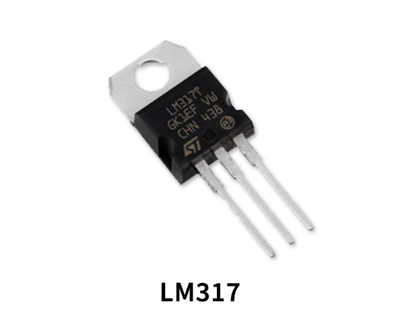
LM317T Pinout

For a detailed description of pinout, dimension features, and specifications download the datasheet of LM317T
2N2907 Pinout

For a detailed description of pinout, dimension features, and specifications download the datasheet of 2N2907
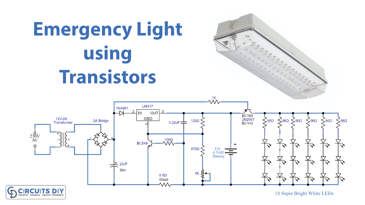
Emergency Light Circuit
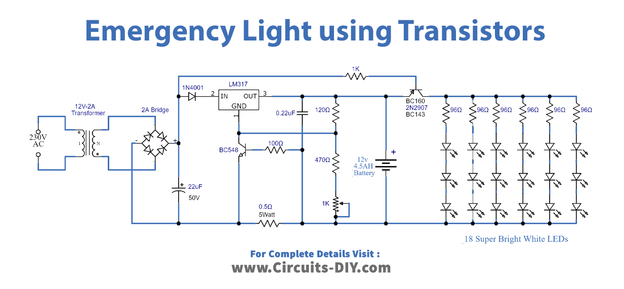
Working Explanation
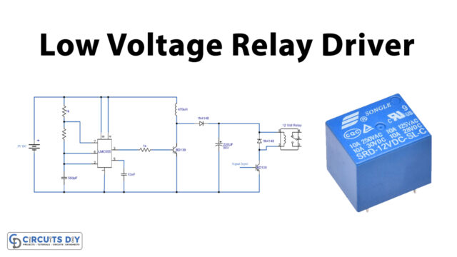
The first part of this circuit is a 12V battery charger circuit stage which is used for charging the 12V 4.5AH lead-acid battery used for the LEDs. A transformer is used for stepping down the voltage from 230V to 12V and a diode bridge is acting as a rectifier. LM317T is used for voltage regulation. The maximum output current of the charger circuit is 1 ampere which is adjustable by the variable resistor of 1K. The output of this circuit charges the battery.
The second part of this circuit contains all the LEDs. PNP transistor is used between the battery and LEDs which acts as a switch. When there is no power from the main supply the transistor will switch ON which will connect the battery with the LEDs and they will light up. This circuit will give more than 24 hours of continuous backup with a 12V Battery and 18 LEDs.
Applications and Uses
It is a compact and efficient circuit and can be used for a lot of purposes. Such as an Emergency lamp, or portable lamp, or can also be used as an LED table/reading lamp.