Introduction
Are you ready to make some noise? Because that’s exactly what we’re going to do in this tutorial on simple electronic gong circuits. These circuits are perfect for anyone looking to add some fun and unique sounds to their electronic projects.
Whether you’re a beginner just starting with electronics or an experienced maker looking for new challenges, these circuits are sure to be a hit. In this tutorial, we’ll dive deep into the world of electronic sound-making and learn how to build two gong circuits you can use for your projects. So, please put on your thinking cap, and let’s get started on building our own electronic gongs!
Hardware Required
You will require the following hardware for 2 Simple Electronic Gong Circuits.
| S.no | Component | Value | Qty |
|---|---|---|---|
| 1. | IC | NE555 Timer, LM741 | 1, 2 |
| 2. | Capacitor | 1n, 10u, 220uF | 1, 2, 1 |
| 3. | Polar Capacitor | 2.2, 10uF | 1, 1 |
| 4. | Resistor | 1K, 10K, 180K, 18K, 15K | 1, 2, 1, 2, 2, |
| 5. | Variable Resistor | 100K, 1M | 2, 1 |
| 6. | Diode | 1N4148 | 2 |
| 7. | Jumper Wire | – | 1 |
| Components | Value | QTY |
| IC | 4093 | 4 |
| Polar Capacitor | 10,000uF | 1 |
| Non-Polar Capacitor | 470nF | 3 |
| Resistor | 150k, 1M | 3, 1 |
| Transistor (MOSFET) | BUZ11A, B7000 | 2, 1 |
| Inductor | – | 2 |
| Diode | 1N4007 | 2 |
| Battery | – | 1 |
| Jumper Wire | – | 1 |
Working Explanations
Here are the working explanations of both circuits given above:
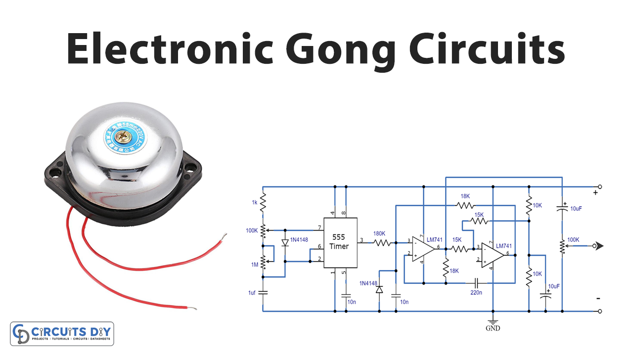
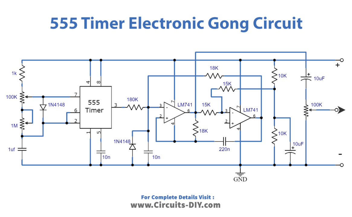
Circuit 1
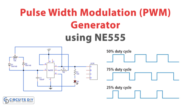
This circuit is used to make a sound similar to that of a bell or a gong. It has a special filter, made up of IC2 and IC3, which creates the sound when a short pulse is added to the input. A 555 timer is used as a switch to provide the trigger pulse, but other types of switches can also be used depending on the project.
Two things control the character of the sound: the “Q” of the filter, which can be changed by adjusting the value of R2, and the length of the trigger pulse, which can be changed by using the P1 knob. The rate at which the gong sound is made can be changed by adjusting the P2 knob. To play the sound through a speaker, the circuit’s output must be connected to an audio amplifier. The overall volume can be adjusted using the P3 knob, which ranges from 0 to 5V.
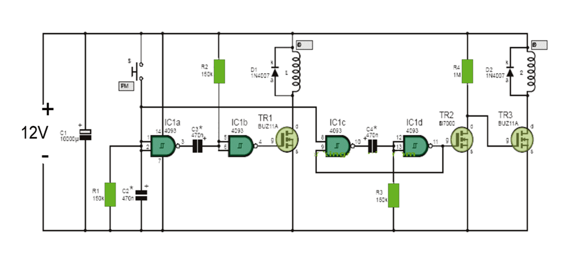
Circuit 2
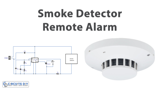
This circuit is an electronic gong that activates two solenoids in sequence. When the front doorbell push button (S1) is pressed, capacitor C2 immediately charges. This prevents the switch from bouncing, which could cause solenoid L2 to activate prematurely. IC1a and IC1b form a positive-edge-triggered monostable timer, which means that when pins 1 and 2 go high, transistor TR1 conducts for a very short period of time, triggering solenoid L1.
Diode D1 is included to prevent back-EMF from damaging IC1. When the push button (S1) is released, capacitor C2 discharges through resistors R1, IC1c, and IC1d, with the help of transistor TR2. This forms a positive-edge-triggered monostable timer so that when pin 8 goes low, TR2 stops conducting. This causes the gate of TR3 to go high and TR3 to conduct, triggering solenoid L2 for a short period of time.
Diode D2 is included to reduce back-EMF. N11-polarized capacitors are recommended for C2 to C4 to avoid any issues with polarity. However, the circuit shows the polarity in case the builder can only find electrolytic capacitors of that value.
If the pulses that activate L1 and L2 are not long enough, the values of resistors R2 and R3 can be increased and vice versa. If transistors TR1 and TR3 are not available, close equivalents can be used. Equivalents must be chosen carefully for TR2, as it is a miniature MOSFET. An NPN bipolar transistor can also be used. But the value of resistor R4 should then be lowered to around 1K to reduce power usage during standby.
Final Words
This guide has gone through the basics of constructing two distinct electrical gong circuits, including what you’ll need, how to do it, and some essential things to keep in mind along the way. Ask away any questions in the comment section, and we’ll try our best to answer!