Introduction
To get the definite frequency and amplitude in various electronic circuits, oscillator circuits become part of those circuits. Thus it plays a crucial role in different microcontroller applications. These oscillators are classified into many types. For example, linear oscillators and non-linear oscillators. The linear oscillators are further classified into other different types like Hartley oscillators, Armstrong oscillators, negative resistance oscillators, Colpitts Oscillator circuits, etc. So, in this tutorial, we are going to “Colpitts Oscillator Circuit”
Brief Overview of Colpitts Oscillator
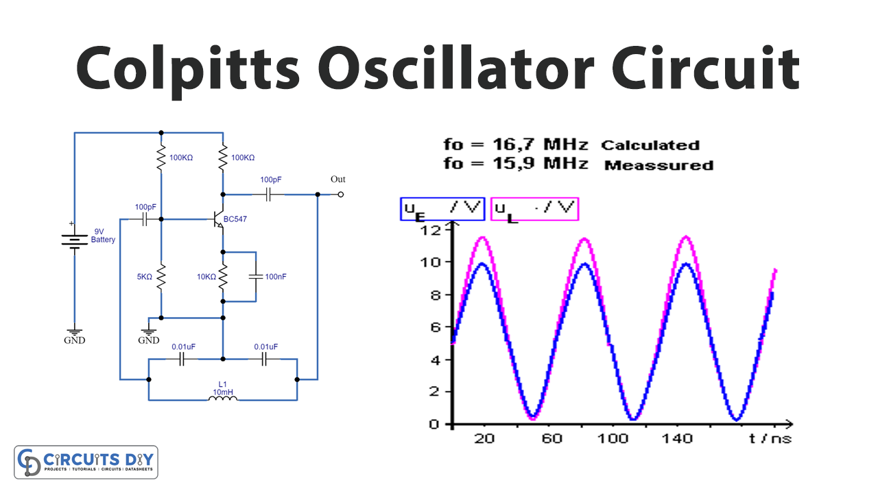
As we have discussed earlier the Colpitts oscillator belongs to the linear oscillator. Hence it oscillates on one frequency. The circuit of Colpitts uses an inductor and capacitors. This oscillator comprises a tank circuit which is an LC resonance circuit made with the help of two capacitors in series with an inductor connected in parallel. These inductors and capacitors determine The frequency of oscillations.
Hardware Required
| S.no | Component | Value | Qty |
|---|---|---|---|
| 1. | NPN Transistor | BC547 | 1 |
| 2. | Inductor | 10mH | 1 |
| 3. | Capacitors | 0.01μF, 100pF, 100nF | 2, 2, 1 |
| 4. | Resistor | 100KΩ, 5KΩ, 1KΩ, 10KΩ | 1, 1, 1, 1 |
| 5. | 2-Pin Connector | – | 2 |
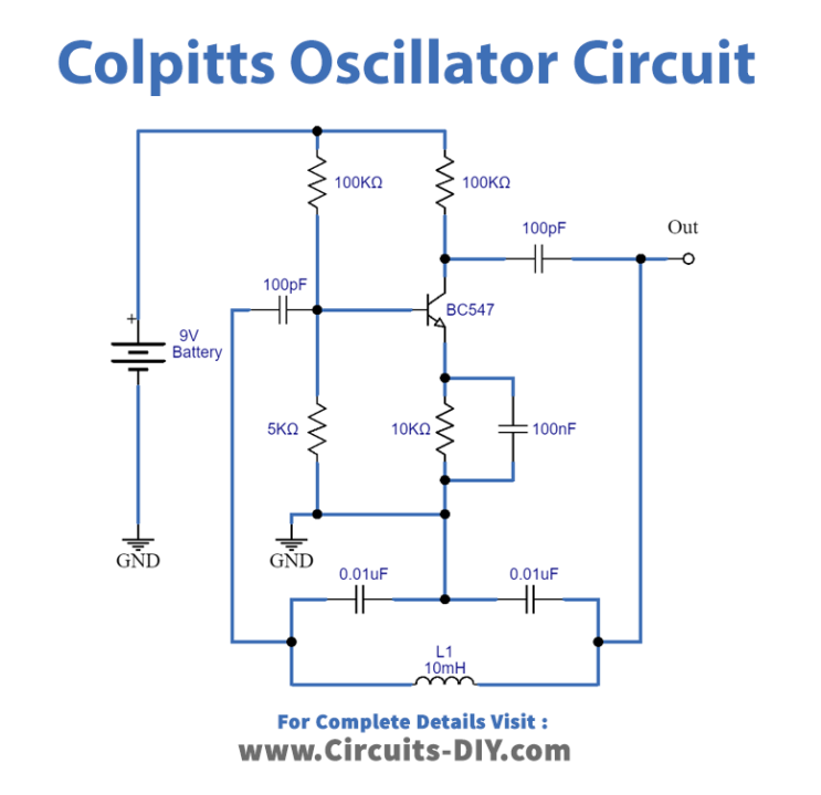
Circuit Diagram
Working Explanation
The Colpitts Oscillator Circuit comprises an RC coupled amplifier with a common-emitter configuration transistor. It also includes the tank circuit. When we provide the power supply, the capacitors C1 and C2 of the circuit charge and when those capacitors become fully charged, the capacitors discharge through the help of inductor L1 which is connected in parallel with those capacitors in this circuit. Thus, an AC voltage is generated across those capacitors by the oscillatory current in the tank circuit. While these capacitors get entirely discharged, the electrostatic energy stored in the capacitors gets transferred as a magnetic flux to the inductor and then the inductor gets charged. In the same way, when the inductor gets discharged, this charged again the capacitor and this entire process generate oscillations.
Application and Uses
- To generate sinusoidal signals of desired frequencies.
- Mobile and radio communication applications.
- We prefer this oscillator in conditions where it should withstand high and low temperatures frequently.
- Applications where a wide range of frequencies are involved.