
A darkness detector is a circuit that detects darkness using light-dependent resistors, it’s used to automatically turn on the lights when it becomes dark.

Hardware Components
The following components are required to make Darkness Detector Circuit
| S. NO | Component | Value | Qty |
|---|---|---|---|
| 1. | Breadboard | – | 1 |
| 2. | Battery | 9v | 1 |
| 3. | Connecting Wires | – | 1 |
| 4. | IC | NE555 Timer | 1 |
| 5. | LDR | – | 1 |
| 6. | Piezo Buzzer | – | 1 |
| 7. | Resistors | 10k, 2.2k, 1M | 1, 1, 1 |
| 8. | Electrolytic Capacitor | 1uF/50V | 1 |
| 9. | Ceramic Capacitor | 0.1nF | 1 |
555 IC Pinout

For a detailed description of pinout, dimension features, and specifications download the datasheet of 555 Timer
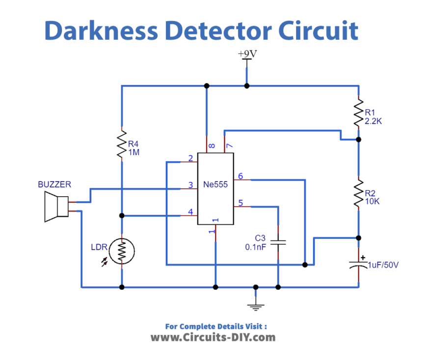
Circuit Diagram
Useful steps
- The circuit uses LDR and 555 Timer IC. timer 555 IC has 8 pins.
- Connect pin 8 to 9 V power supply.
- Connect pin 1 to GND.
- Place a 2.2 KΩ resistor in between the 9V battery and pin 7 of the timer IC.
- Connect a 10 KΩ resistor between pins 6 and 7.
- Short the pins 2 and 6.
- Place a capacitor of capacitance 1 µF in between pins 2 and GND.
- Connect the positive leg of the capacitor to pin 2 of the timer IC & negative to GND.
- Place a bypass capacitor of 100pF in between GND and pin 5
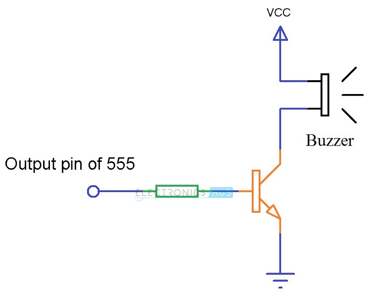
- Connect a piezo buzzer in between the GND and pin 3.
Working Explanation
- Timer IC is configured in Astable mode. LDR controls the reset pin.
- When LDR detects enough light, its resistance becomes low.
- In this experiment, the resistance drops to 2K. In this case, there will be 0 voltage at the output generated by the 1M ohm resistor and LDR.
- This voltage is fed to the reset pin and it triggers the reset of timer IC 555. Thus, there won’t be any output at the output pin.
- If there is an obstacle in the path of LDR, light falling on LDR will decrease and thus, resistance will increase.
- In this experiment, resistance increases to 120k ohm. As a result, the voltage difference will be generated which will be fed to the reset pin.
- The reset pin gets to pull up and the astable mode activates.
- Here, we have connected a buzzer at the output pin of timer IC 555, so the buzzer will also be activated in this case.
Applications
- Used in locations where automatic switching of light is required.
- Used as a security measure in homes, buildings, or workplaces.
- Used in home automation services.


