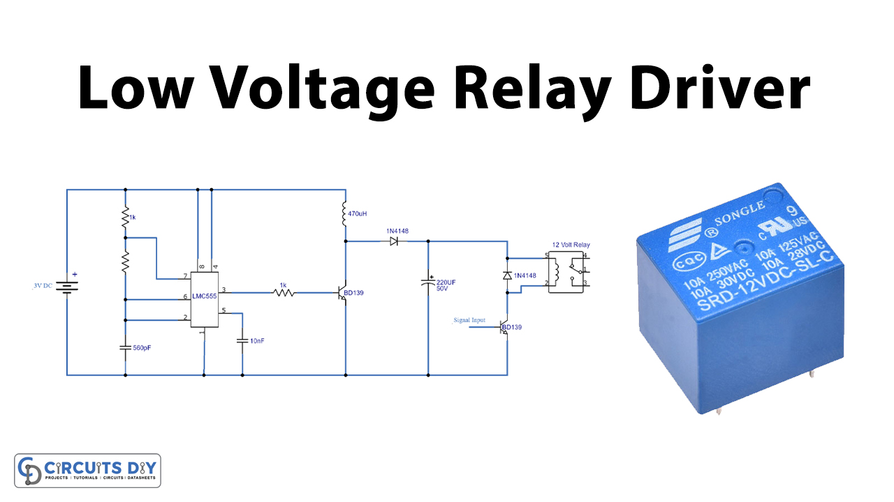
Driving a 12V relay with a 3V supply is a common engineering practice. It is usually seen in small-scale electronics, the Process industry & academic settings. So, in this project, we will understand driving a 12V relay with a 3V supply using LMC 555 CMOS Timer IC.
LMC 555 Timer IC possesses an oscillation frequency ranging from 670 to 680 Hz. Here, this 555 timer acts as an astable multivibrator An astable multivibrator is a free-running oscillator that switches continuously between its two unstable states. With no external signal applied, the transistors alternately switch from cutoff to saturation state at a frequency that RC time constants of the coupling circuit determine. If these time constants are equal (R and C are equal) then a square wave will generate with a frequency of 1/1.4 (RxC). Hence, an astable multivibrator is also a pulse generator or a square wave generator.
Hardware Components
The following components are required to make a 12V Relay Driver Circuit
| S.no | Component | Value | Qty |
|---|---|---|---|
| 1. | Timer IC | LMC555 | 1 |
| 2. | NPN Transistors | BD139 | 1 |
| 3. | SPDT Relay | 12V | 1 |
| 4. | Diode | 1N4148 | 1 |
| 5. | Inductor | 470uH | 1 |
| 6. | Breadboard | – | 1 |
| 7. | Connecting Wires | – | – |
| 8. | Capacitors | 22uF/50V, 10nF, 560pF | 1 |
| 9. | Resistors | 10K, 1K | 1 |
| 10. | Battery | 3V | 1 |
| 11. | Battery Clips | – | 1 |
LMC555 Pinout

For a detailed description of pinout, dimension features, and specifications download the datasheet of LMC555
12V Relay Driver Circuit
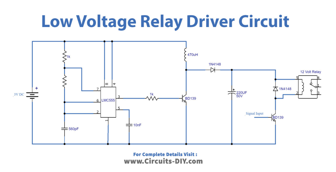
Working Explanation
The heart of this circuit is an LMC555 Timer IC. The IC requires a minimum input supply of at least 1.5V. On connecting to power (3V), the IC produces a Constant square wave clock due to being in astable multivibrator mode. This square wave signal (12V) acts as a control signal for transistor Q1 (BD139). The collector output of the transistor Q1 moves on towards the 12V SPDT relay.
In order to trigger the relay, we provide an input control signal to transistor Q2 (BD139) & the relay actuates, here a 1N4148 diode protects the SPDT relay from negative feedback. The circuit will work with all low voltage projects for example with CMOS and Arduino projects and any other 3V projects. It can also be used to drive different voltages relays with 3V DC.
Applications
- An important part of various procedures requiring control through a nominal voltage source (3V) such as automation procedures in the process industry.