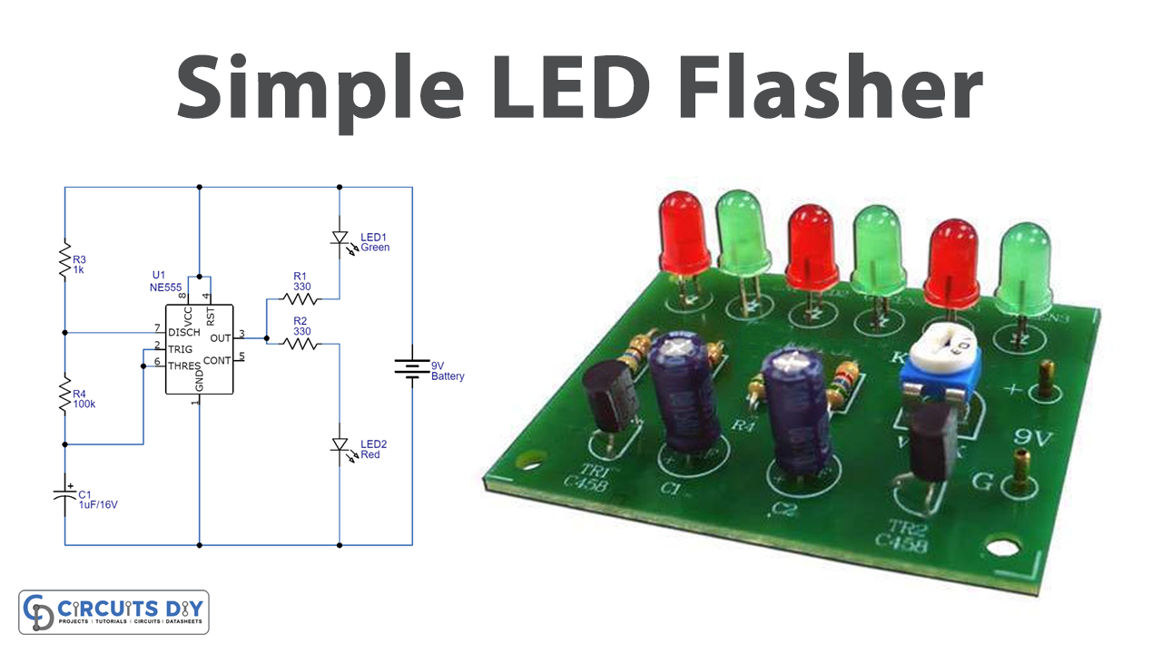
Introduction
In electronic devices, we usually use LEDs for signs or indications. Though, there are also some major projects that are totally based on LEDs. For example, the flasher circuits or the flashing lights units using LEDs. We generally have seen these sorts of circuits in art, decoration, or children’s toys. For instance, they get used in homes at weddings, birthday parties, etc. The flasher circuit plays an artistic role.
You may also observe these kinds of circuits in police mobiles and ambulances to alert the people around. Because of so many good reasons, we have thought that in this tutorial, we are going to “Simple LED Flasher Circuit”

Hardware Components
The following components are required to make LED Flasher Circuit
| S.no | Component | Value | Qty |
|---|---|---|---|
| 1. | IC | NE555 Timer | 1 |
| 2. | LED | – | 2 |
| 3. | Capacitor | 1uF/ 16v | 1 |
| 4. | Resistor | 330Ω, 1KΩ, 100KΩ | 1,1,1 |
| 5. | Battery | 9V | 1 |
| 6. | 2-Pin Connector | – | 1 |
NE555 IC Pinout

For a detailed description of pinout, dimension features, and specifications download the datasheet of 555 Timer
LED Flasher Circuit
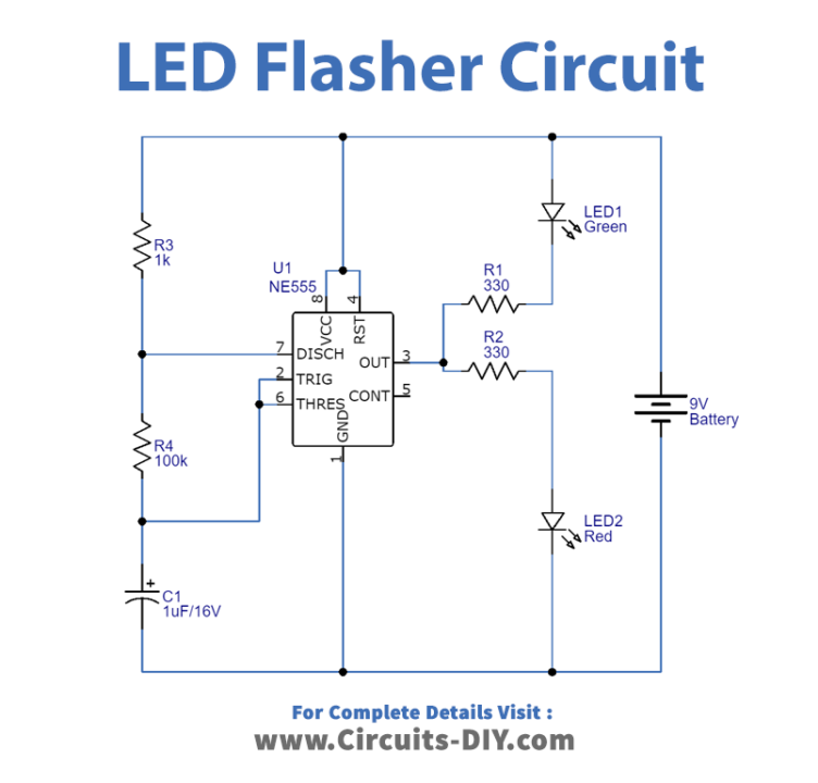
Working Explanation
This Simple LED Flasher Circuit uses the LM555 timer IC, having 8 pins. We give the power supply at pin 8, while pin 1 is for the ground. Pin 4 is the reset pin to apply the Negative pulse to reset the timer IC. Since this circuit it’s not used for reset Purposes, therefore we have wired it to VCC pin 8. Thus, it helps to avoid negative triggering. Pin 6 Compares the voltage to the terminal with the voltage of two-thirds of the VCC. The trigger pin 2 is effective for change of the flip-flop from set to reset. Hence, connected with the threshold pin 6. Output load, that is LEDs are connected at pin 3 of an IC.
Application and Uses
- used for decoration purposes
- In toys of children.
- In signal lights.
- In some display circuits, etc