Introduction
Experimenting with electronics by making simple projects but with little innovation is fun. That’s why we always try to come up with the circuits that may develop the interest of a beginner. Hence, In this tutorial, we are going to “IR Remote Control Light Switch”. Remote controls are the household electronic devices used for television, air conditioning, etc. But, what if you as a beginner try to control the bulb or a light of your room. Sounds good? So, let’s start making the circuit.
However, in this circuit, we have used the TSOP 1738 IR receiver module, so it would be better if we see some of its features.
- This reciever consumes the low power.
- The output of this reciever is active low.
- It has preamplifier and photodetector in one package.
- It allows contionous data transmission uoto 2400bps.
Hardware Required
| S.no | Component | Value | Qty |
|---|---|---|---|
| 1. | IR Receiver | TSOP1738 | 1 |
| 2. | Regulator IC | 7805 | 1 |
| 3. | Timer IC | LM555 | 1 |
| 4. | IC | CD4017 | 1 |
| 5. | Relay | 9v | 1 |
| 6. | NPN Transistor | BC547 | 2 |
| 7. | Diode | 1N4007 | 1 |
| 8. | Capacitor | 0.01μF, 10μF | 2, 1 |
| 9. | Resistor | 100KΩ, 330Ω | 2, 1 |
| 10. | Battery | 9V | 1 |
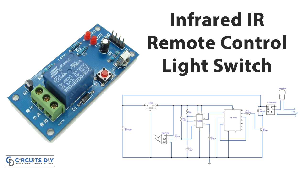
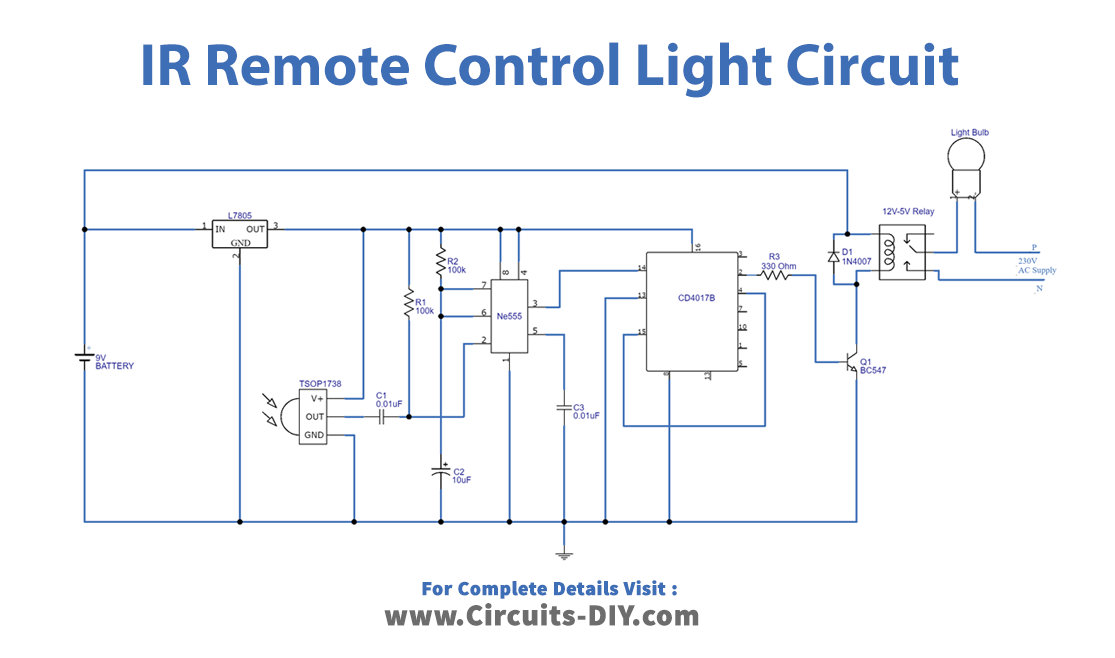
Circuit Diagram
Working Explanation
In this IR Remote Control Light Switch circuit, the first IC LM7805 IC gives the regulated 5V DC supply to the infrared sensor, counter, and timer IC. The output of the TSOP 1738 sensor is connected to the trigger pin of the 555 timer IC. When there is an IR signal, TSOP 1738 received that signal and triggers the 555 timer IC. In this circuit timer, IC is configured in a monostable multivibrator mode, and therefore it generates a single pulse depending on the value of resistor R2 and capacitor C2.
The output coming from the timer IC is then given to the clock pin of the IC 4017 counter. This starts counting the clock. If the count starts from 0, Q1 output becomes. Since the BC547 transistor is connected to Q1 therefore it gets triggered and thus the relay gets the ground supply. Now relay coil gets energized and makes the connection to the normally closed (N/O) contact. So, the bulb gets a power supply and starts glowing.
If the counter after getting a pulse starts the count from one, means Q1 is high already, in that case, Q2 output becomes HIGH and this signal is biased to Reset pin 15 as it is connected to that pin. Now counter gets Reset, so the Q1 becomes low, now the transistor gets turned OFF. Hence relay gets turn OFF, the bulb gets disconnected from the supply, and stop glowing.
To understand it more readily, when there are any infrared signals from Remote Control you can control the electrical appliances. Here we have taken the bulb as an electrical appliance.
Application and Uses
With some more advancements, it can be used in home automation circuits. Hence you can use this to control the appliances of your home. For example,
- To control lights and fans.
- Or to turn on or off radios or television.
- To control washing machines, etc