In this tutorial, we will show how you can make a simple Dark Detector circuit using a 555 timer IC. This circuit indicates the absence of light or the presence of darkness in a certain region. Whenever the intensity of light falling on the Light Dependent Resistor (LDR) is below a certain value, a buzzer connected to the output of the 555 timer IC will produce sound and thereby this circuit will work as a Dark Detector Alarm.

Hardware Components
The following components are required to make Dark Sensor Circuit
| S. NO | Component | Value | Qty |
|---|---|---|---|
| 1. | Breadboard | – | 1 |
| 2. | Battery | 9v | 1 |
| 3. | Connecting Wires | – | 1 |
| 4. | IC | NE555 Timer | 1 |
| 5. | PNP Transistor | 2N3906 | 1 |
| 6. | LDR | – | 1 |
| 7. | Variable Resistor | 500k | 1 |
| 8. | Resistor | 100k, 22k, 10k | 1,1,1 |
| 9. | Capacitor | 100nF | 1 |
| 10. | Speaker | – | 1 |
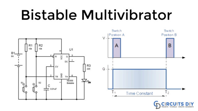
555 IC Pinout

For a detailed description of pinout, dimension features, and specifications download the datasheet of 555 Timer
Circuit Diagram
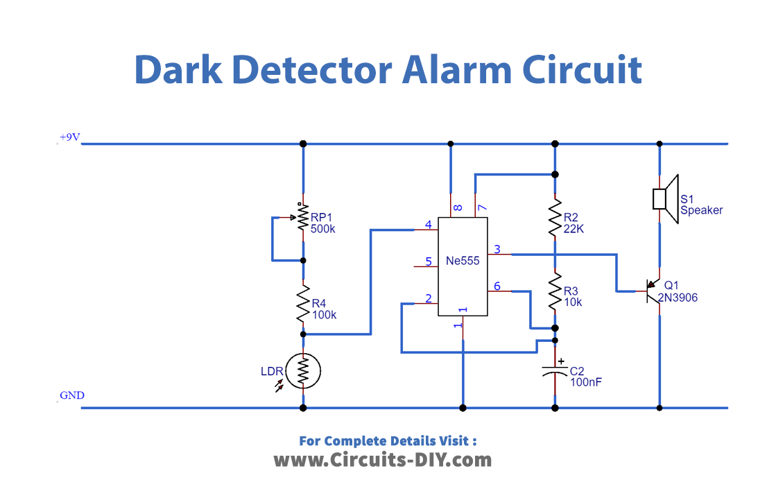
Connection
- Place the 555 timers on the breadboard and connect Pin 8 to VCC and Pin 1 to GND.
- Use a jumper wire to connect Pin 2 and Pin 6.
- Connect LDR in between GND and the potentiometer.
- Connect Pin 3 to the base of the transistor.
- Use a jumper wire to connect the Collector of the transistor to GND.
- Connect the speaker in between the VCC and the Emitter of the transistor.
Working Explanation
The LDR is also known as a photoresistor. It comes in different sizes and its sensitivity depends upon its size. The 555 timers will work as an astable multivibrator in this circuit. When the light falling on the LDR is below a certain level, the LDR will trigger the 555 timers and it will produce square waves at its output and the buzzer will start making a sound. We can also connect an LED instead of a buzzer in this circuit. In order to change the sensitivity of LDR, we have to vary the resistance of the potentiometer.
Applications
- We can employ this circuit at a place, where we need to monitor the change in light intensity.
- This circuit can be used to automatically turn on the light when it becomes dark.