In this DIY, we are demonstrating a project of Door Bell. This project is easy to build and requires a few components that are easily available in the market. In every home, Doorbell is a very popular and useful gadget. The doorbell circuit project is trendy among electronics hobbyists and enthusiasts.
So we will build a doorbell with 555 time IC in this tutorial. The key characteristic of this doorbell is to control the time for which the switch is pressed. We may also control the frequency of the oscillation of the Doorbell’s “doorbell signal” signal (we use Buzzer as a stick here).

Hardware Component
The following components are required to make Door Bell Circuit
| S.no | Component | Value | Qty |
|---|---|---|---|
| 1. | Battery | 5- 9 V | 1 |
| 2. | Push-button Switch | – | 1 |
| 3. | IC | NE555 timer | 2 |
| 4. | Buzzer or Speaker | – | 1 |
| 5. | Resistor | 1K, 10K, 100K, 10K Var | 1, 1, 1, 1 |
| 6. | Capacitor | 1uF, 1000uF | 1, 1 |
| 7. | LED | – | 1 |
NE555 IC Pinout

For a detailed description of pinout, dimension features, and specifications download the datasheet of 555 Timer
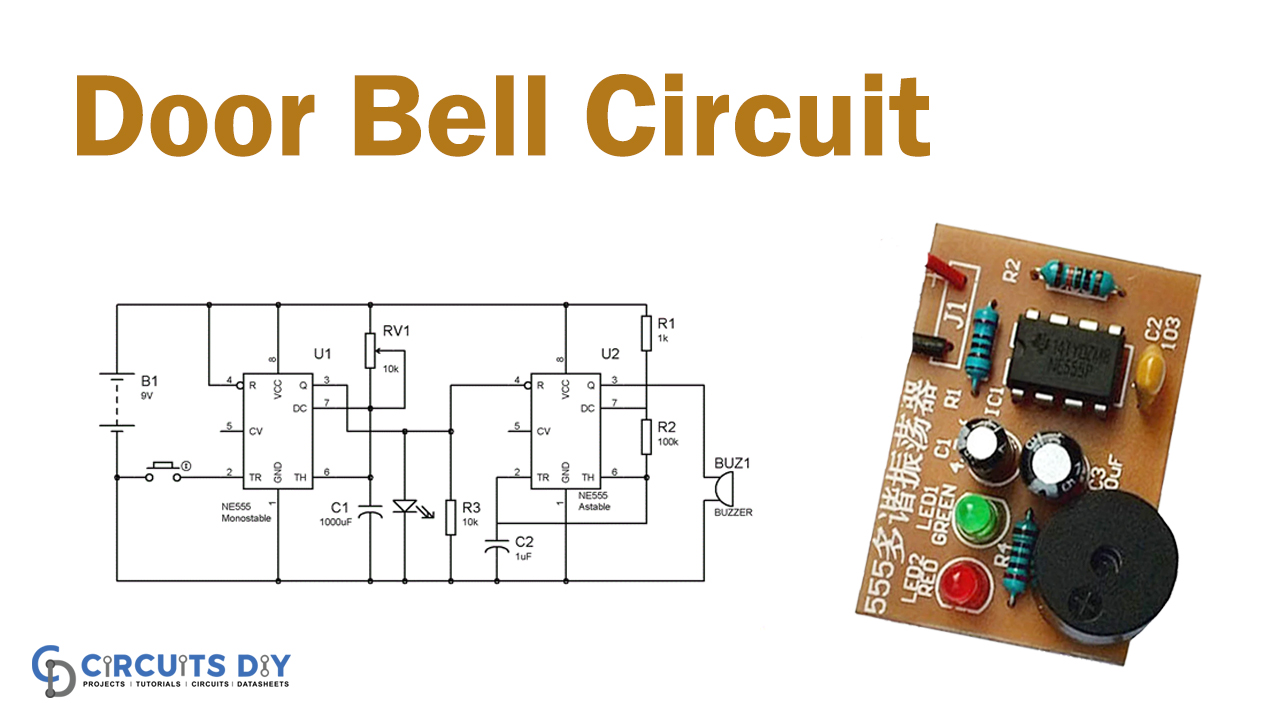
Door Bell Circuit
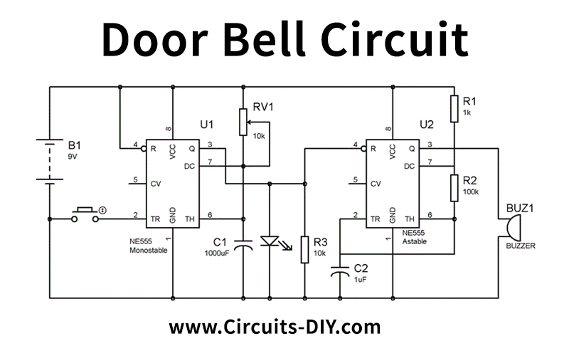
Working Explanation
The circuit diagram for the doorbell shows above. Here, we can see that the First 555 timer IC in Monostable mode is programmed so that when triggers pin 2, it is only high and low once. The ring period is controlled by the RV1 variable resistor, which indicates how long the output pin 3 will be high. Input PIN 3 will be HIGH before the capacitor is loaded up to 2/3 Vcc battery voltage while Output Pin 3 is LOW before the capacitor is discharged to 1/3 Vcc, says the IC Principal of 555 timers. This charging and discharging are performed in the Monostable mode once. And in Astable mode, it still happens.
Applications and Uses
A doorbell is usually mounted near a door to the entrance of a house. The bell rings inside the building as a visitor presses a button alerting the resident to the visitor’s presence.