Introduction
Tick! Tick! Tick. Well, on sleepless nights one sound that bothers all of us a lot is the ticking sound of a clock. But, if electronics have ever inspired you then on those nights you must have thought about the circuit of that sound. So, if you are interested in that circuit, read the entire article, because, in this tutorial, we are going to “Clock Ticking Sound Circuit using 555”. The 555 timer IC is one of the most used ICs in the electronic circuits world. It’s an integrated circuit that has so many applications in timer, delays, oscillator, and pulse generator. The integrated circuit contains 8 pins having different definitions. The favorable aspect of this IC is that it’s reasonable in price and easy to handle.
Hardware Required
| S.no | Component | Value | Qty |
|---|---|---|---|
| 1. | IC | NE555 Timer | 1 |
| 2. | Speaker | 8 ohms | 1 |
| 3. | Capacitor | 10μF | 2 |
| 4. | Resistor | 43KΩ | 1 |
| 5. | Battery | 9V | 1 |
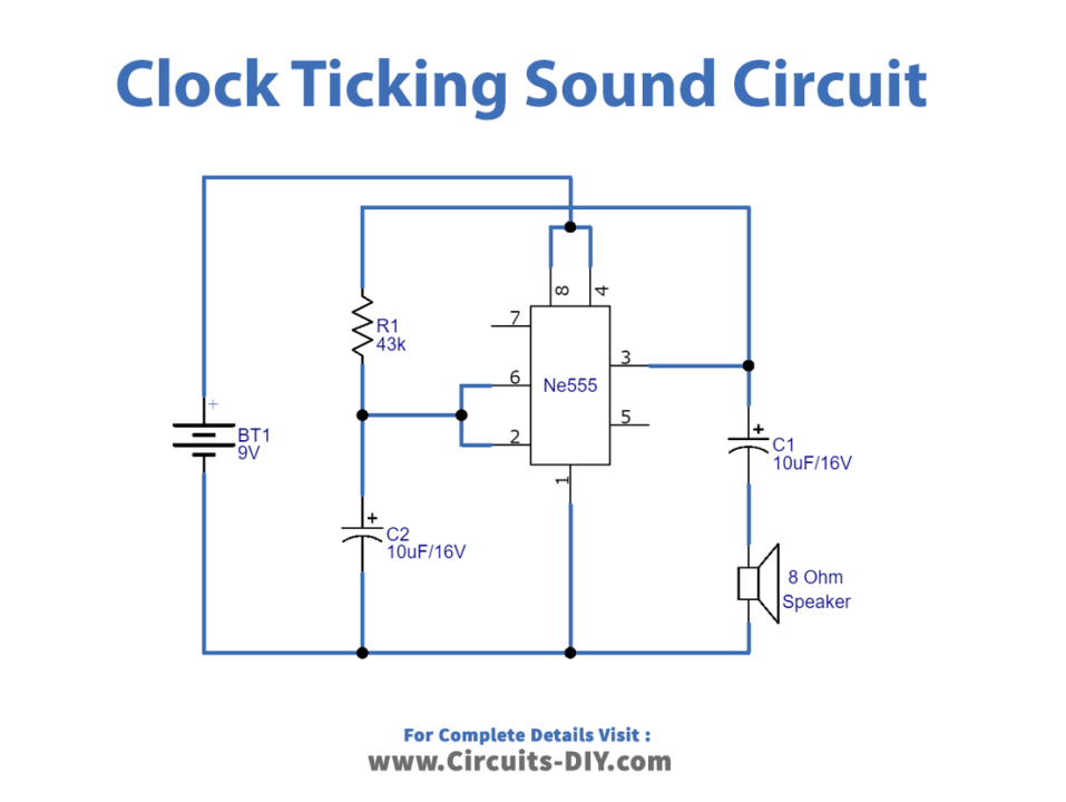
Circuit Diagram
Working Explanation
This circuit is the same as any timer circuit, including the buzzer. To build this Clock Ticking Sound Circuit using 555, the IC is working as a monostable multivibrator. And, for this, connect trigger pin 2 to the ground supply with the help of the capacitor. When there is a supply, IC starts its operation. The trigger pin and threshold pin are connected and then get wired to the capacitor C2. We connect the output pin to the8 ohms speaker using a 10-10uf capacitor that drives the speaker. We connected VCC and reset pins with the positive terminal of the 9V battery. While we connected to pin 1 with the ground of the 9V battery
Application and Uses
- We use it in wall clock circuits.