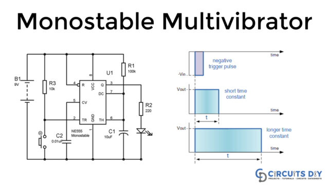
The most effortless mode of 555 timer IC is the Bistable Multivibrator mode. As we have discussed before that the monostable mode of 555 timer IC has one stable and one quasi-stable state, and the astable mode has both the unstable states but in bistable multivibrator mode; we have both the stable states. Until an external trigger is applied, it will remain in the same state, either high or low. There are no equations and waveforms in this mode because of no RC network in it.
In this tutorial, we are demonstrating the project of a 555 Timer Bistable Multivibrator Circuit, which is easy to demonstrate.

Hardware Component
The following components are required to make Bistable Multivibrator Circuit
| S.no | Component | Value | Qty |
|---|---|---|---|
| 1. | LED Diode | – | 1 |
| 2. | Switch | – | 2 |
| 3. | Battery | 9 V | 1 |
| 4. | IC | NE555 timer | 1 |
| 5. | Capacitor | 10uF, 0.01uF | 1, 1 |
| 6. | Resistor | 10K, 220 ohms | 2, 1 |
NE555 IC Pinout

For a detailed description of pinout, dimension features, and specifications download the datasheet of 555 Timer
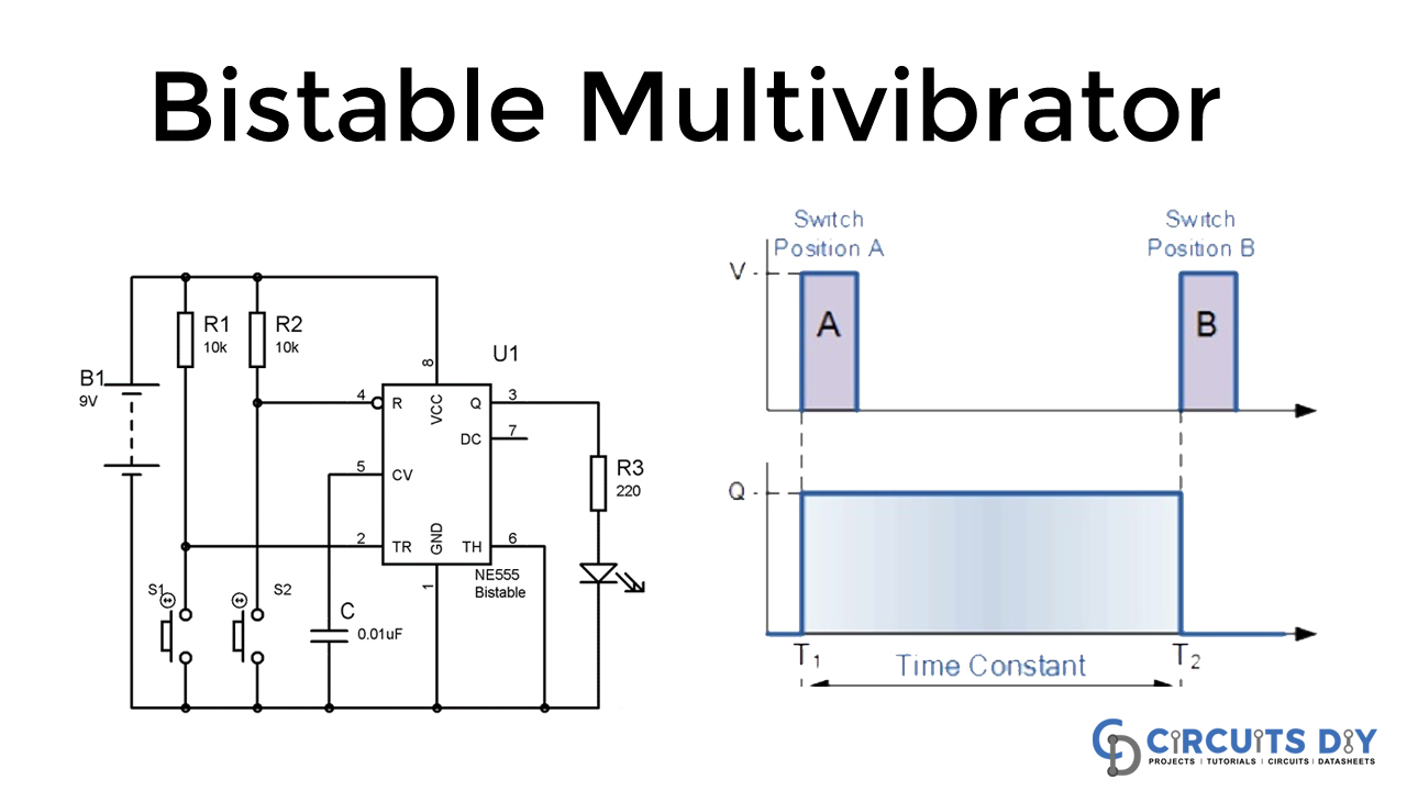
Bistable Multivibrator Circuit

Circuit Operation
As referenced, it is the most straightforward mode and doesn’t need any RC circuit. The states are constrained by the Trigger PIN 2 and the RESET PIN 4. Trigger PIN 2 is the upsetting finish of the LOWER comparator inside 555 timer IC and RESET Pin 4 is the RESET terminal of the RS flip flop. Trigger PIN is utilized to SET the flip flop, which will give output high, and Reset Pin is utilized to Reset the flip flop, which provides the output with low. Push buttons S1 and S2 are associated with the Trigger Pin and Reset Pin individually, to make them LOW. The output is set by pushing switch S1 and the output is reset by pushing the switch S2.
Applications and Uses
It has two stable states, which are low or high (0 or 1), so it can be used for storing binary digits. It is named Flip flop or Latches and is used in digital circuits.