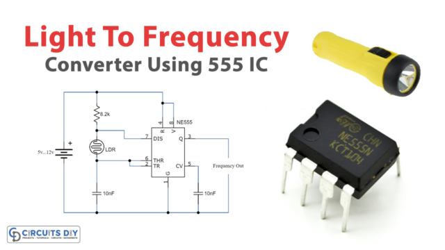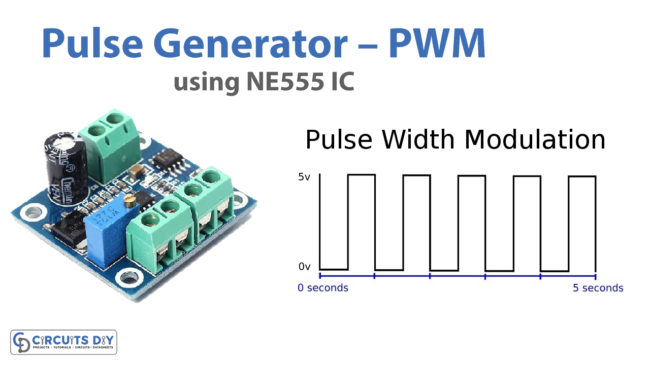
Today in this article we are going to generate a pulse using a 555 Timer IC. The circuit can be used with any project, which requires positive pulses. An LED is used at the output of the IC to show the visual indication of the output pulses.
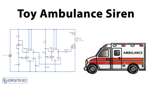
The heart of the circuit is a famous 555 IC that is wired as an astable multivibrator here. The output frequency of pulses can be adjusted with a 100K variable resistor. A 100K pot can also be used in the place of a 100K resistor to adjust the circuit smoothly. The pulse frequency also depends on R1 and C1. The circuit can be operated from any voltage from 5 to 15 volt DC.

Hardware Components
The following components are required to make Pulse Generator Circuit
| S.no | Component | Value | Qty |
|---|---|---|---|
| 1. | IC | NE555 Timer | 1 |
| 2. | Resistors | 5.1k,1.2k,1k, | 1 |
| 3. | Electrolytic Capacitor | 10uf | 1 |
| 4. | Ceramic Capacitor | 0.1uf | 1 |
| 5. | Potentiometer | 100k | 1 |
| 6. | Power Supply | 5-15v | 1 |
NE555 IC Pinout

For a detailed description of pinout, dimension features, and specifications download the datasheet of 555 Timer
Pulse Generator Circuit

Application & Uses
- PWM Techniques are used in Telecommunications for encoding purposes.
- Pulse Width Modulation helps in voltage regulation and thus finds its use in controlling Brightness in Smart Lighting Systems and also controls the speed of motors.