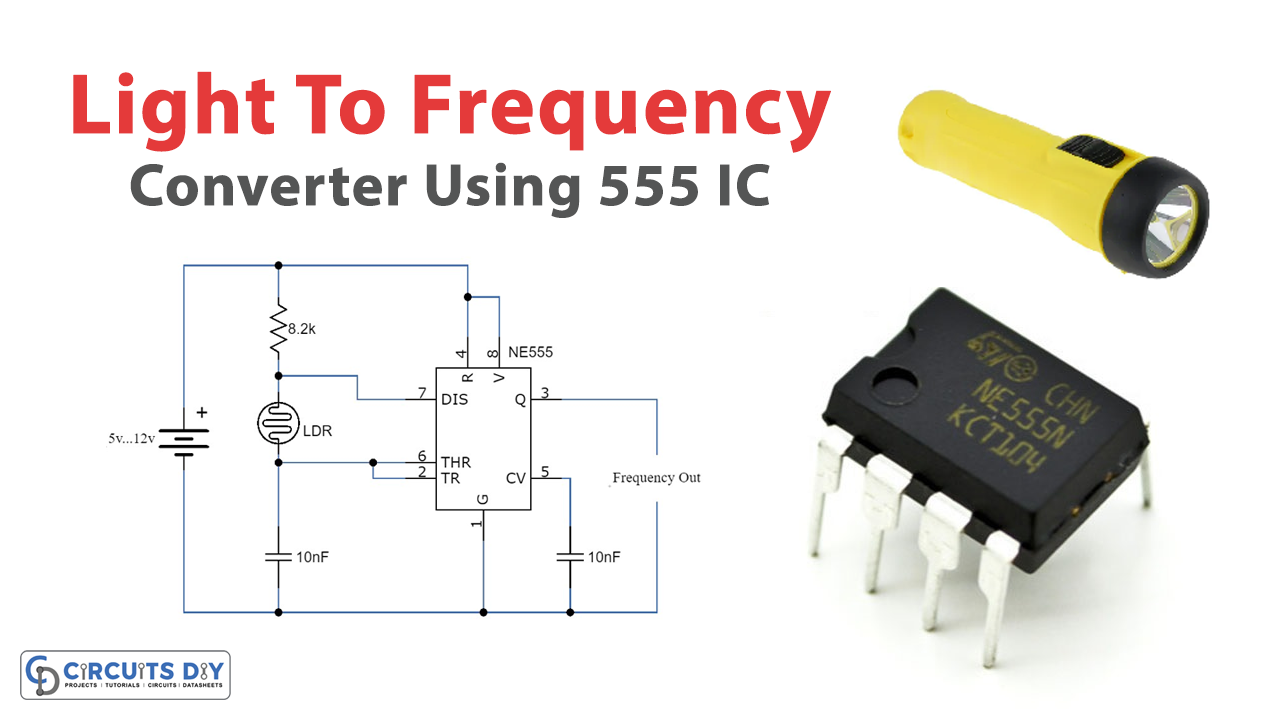
Here we are making a circuit of a Light Frequency Converter Using 555 IC. The purpose of this circuit is to convert light signals to frequency, this method is used in a lot of electronic applications for better processing of an incoming signal. This can be performed by different devices available in markets, to convert light signals into frequency signals we use TSL235R, which is a readymade light-to-frequency converter. But we can also make it by ourselves by using only a few components like 555 timer IC, LDR, and a few other discrete components as shown in the circuit diagram.

Hardware Components
The following components are required to make the Light Frequency Converter Circuit
| S.no | Component | Value | Qty |
|---|---|---|---|
| 1. | Input Supply | 5-12V | 1 |
| 2. | Resistor | 8.2K | 1 |
| 3. | Ceramic Capacitor | 10nF | 2 |
| 4. | IC | NE555 Timer | 1 |
| 5. | LDR | – | 1 |
NE555 IC Pinout

For a detailed description of pinout, dimension features, and specifications download the datasheet of 555 Timer
Light to Frequency Converter Circuit
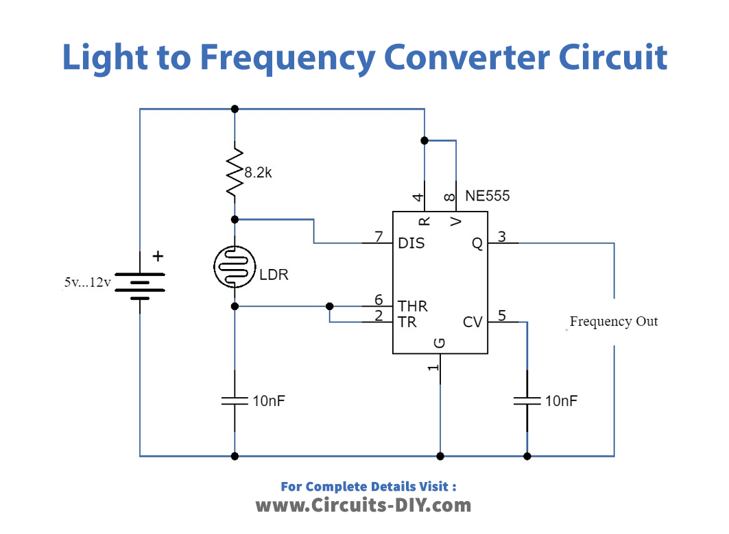
Working Explanation
This circuit can be operated at DC voltages ranging from 5 to 12V. The output frequency of the 555 timer IC is directly proportional to the light received by the LDR. LDR’s internal resistance increases in the dark or when there isn’t much light falling onto its surface so at that time the output frequency of the 555 IC will decrease. Similarly, when there is light present or falling onto the LDR its resistance will decrease and the output frequency of the 555 timers will increase. However, the different frequency spectrums can be selected by changing the values of the resistor and capacitor between pin 6 of the IC and the negative rail of the supply. The output of this circuit can be fed to a microcontroller or digital circuit for further processing the signal or to enhance it more. A photodiode can be used instead of an LDR.