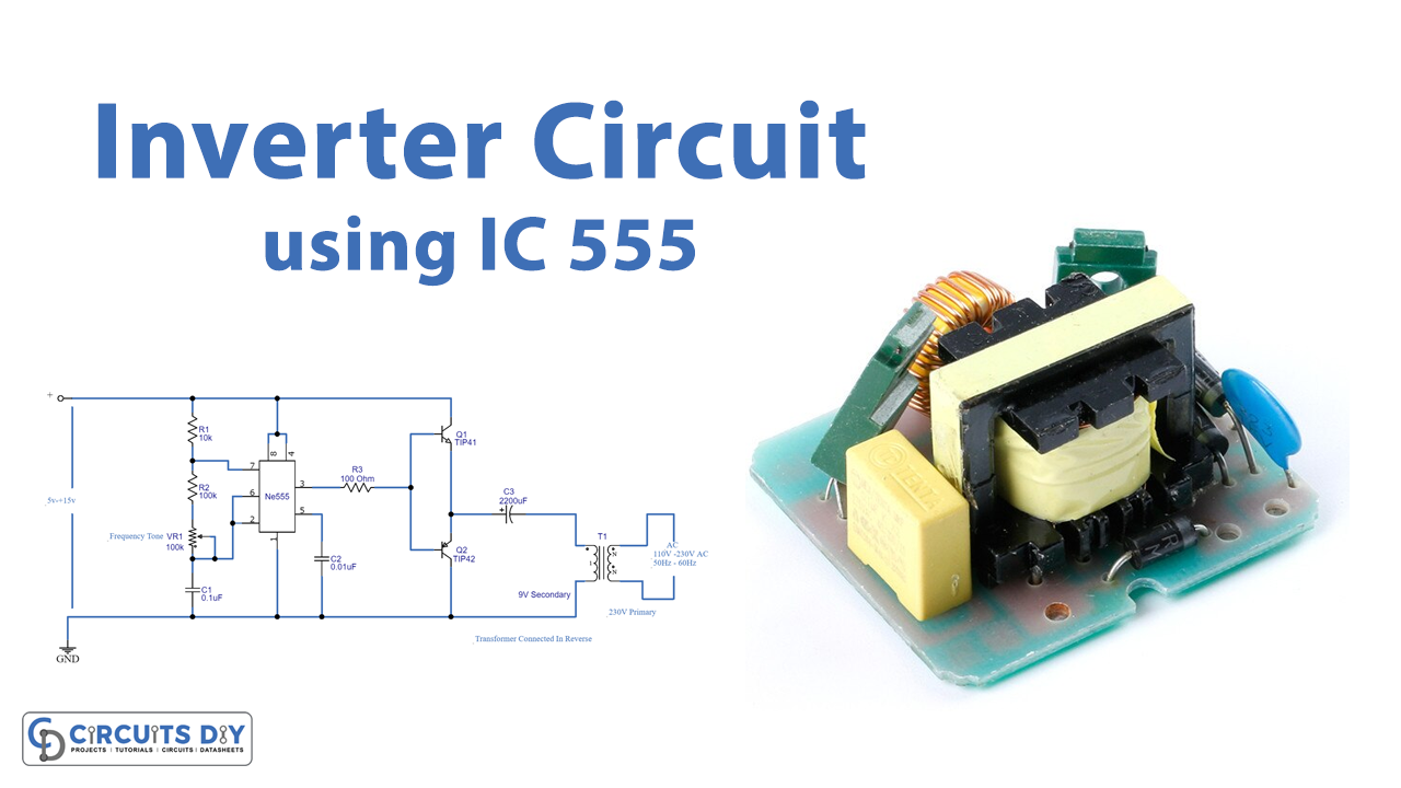
Introduction
Assume you’re working on a DC-powered project when you suddenly realize you’ll need an AC component in your circuit. An AC light or an AC motor might be the source of the problem. What would you do in this situation? You’ll need an AC supply for that, but your device already has a DC supply. As a result, you’ll need an AC inverter circuit. So, We’ve created this interesting “Simple Inverter Circuit using IC 555” to help you comprehend the entire circuitry.
It just takes a few components that are readily accessible at low rates. The following circuit can be used in UPS and other DC-to-AC converter applications with few modifications.
Hardware Required
| S.no | Component | Value | Qty |
|---|---|---|---|
| 1. | IC | NE555 Timer | 1 |
| 2. | Transformer | 5v-15v | 1 |
| 3. | Transistor | TIP42A | 4 |
| 4. | Transistor | TIP41A | 1 |
| 5. | Potentiometer | 50K | 1 |
| 6. | Capacitor | 0.01uF, 0.1uF | 1, 1 |
| 7. | Electrolysis Capacitor | 2200uF | 1 |
| 8. | Resistor | 100Ω, 10KΩ, 100KΩ | 1, 1, 1 |
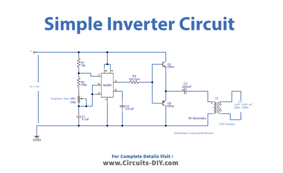
Circuit Diagram
Working Explanation
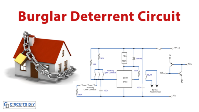
The major component in this Simple Inverter Circuit using IC 555 is the timer IC555, which is set as an Astable Multivibrator to provide a continuous switching pulse. Two switching transistors TIP41A (NPN) and TIP42A (PNP) drive the transformer according to the pulse input at the base. T1 is a 230V primary to 9V secondary transformer that is wired in reverse to operate as a step-up transformer. We may supply a 5V to 15V DC bias to this circuit to get 110V to 230V AC at 50Hz to 60Hz, but the output may not be a pure sine wave like the PWM inverter output; instead, it will be pulsated AC. The VR1 potentiometer is there to change the output frequency of this circuit. So, you can adjust the frequency by adjusting this potentiometer.
Application and Uses
- It may be used to run AC appliances.
- This easy project may be used to control the AC lights or a light bulb.
- We may utilize it in power supplies, UPS circuits, and other applications with simple modifications.