
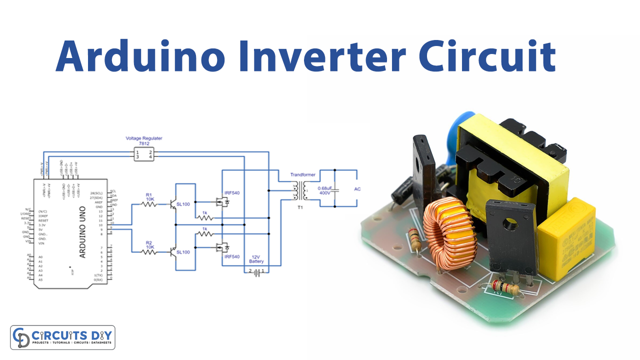
In this tutorial, we are going to make an “Arduino based Inverter Circuit”.
An inverter is an electrical device that converts DC voltage. Almost always from batteries into standard household AC voltage, so that it is able to be used by common appliances. Inverter circuits are very helpful to produce AC supply when we need them, and it uses the minimum level of DC bias from a battery source. Here we design a simple inverter circuit, which consists of Arduino, a voltage regulator LM 7809 (which gives constant voltage to Arduino board regardless of the battery voltage), two switching transistor SL100 NPN, two MOSFETs IRF540 (which can handle Watt power with a heat sink mounted.
If you want more power, you can choose a more powerful MOSFET) and center-tapped transformer (The transformer’s voltage and current parameters decide the maximum output power). In this simple and reliable inverter circuit, we can program Arduino to obtain stepped AC output, modified sinewave AC output, or pure sinewave output. And also we can program the Arduino board, to bring a different range of frequency output.
Hardware Required
| S.no | Component | Value | Qty |
|---|---|---|---|
| 1. | Voltage Regulator IC | 7812 | 1 |
| 2. | Transistor | SL100 | 2 |
| 3. | Mosfet | IRF540 | 2 |
| 4. | Transformer | 12-0-12 VAC | 1 |
| 5. | Arduino Uno | – | 1 |
| 6. | Resistor | 1KΩ,10KΩ | 2,2 |
| 7. | Connecting Wires | – | – |
| 8. | Battery | 12V | 1 |
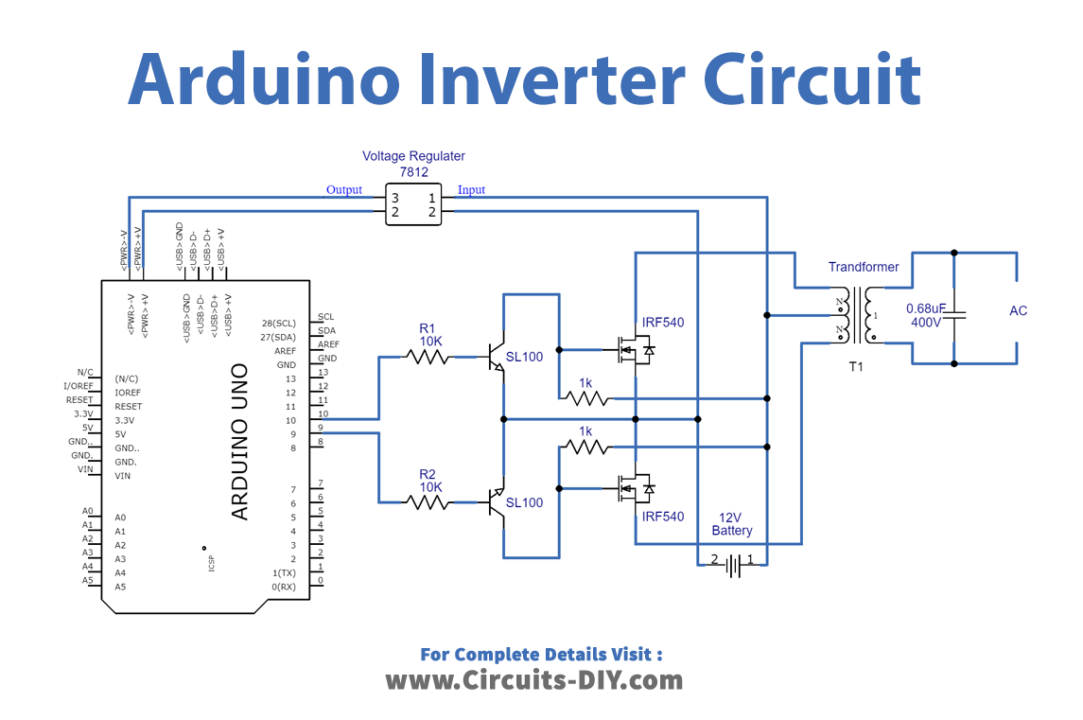
Circuit Diagram
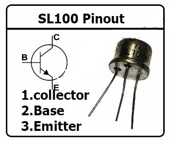
Transistor SL100 Pin Configuration
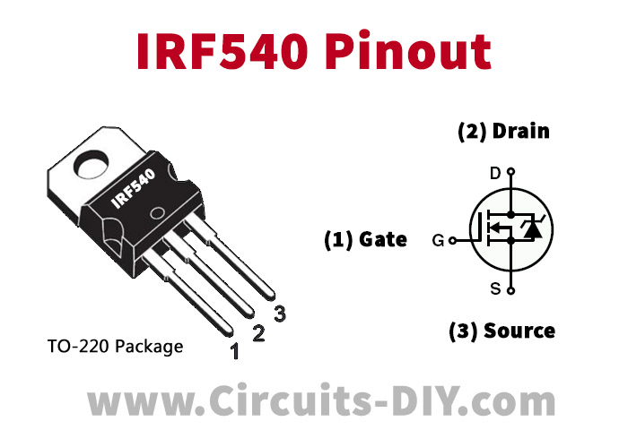
Mosfet IRF540 Pin Configuration
Working Explanation
As we can see in the circuit, there are three stages involved and a 12V 5.0Ah SLA battery as a DC bias. The first stage consists of the Arduino microcontroller board, which is programmed to give SPWM (Sinusoidal Pulse Width Modulation). You can modify the code to produce different outputs from Arduino pins.
The second stage is the switching and driver stage, the output pulse from the Arduino digital pins is fed into the switching transistor SL100 NPN. And then powers MOSFET IRF540.
The third stage is the output stage, which is constructed by using a center-tapped transformer (230 VAC primary / 12-0-12 VAC secondary). It is connected reversely with the driver circuit, that is a secondary side (12-0-12 VAC) is connected to the power MOSFET and the primary side of the transformer is left to give output supply.
When the battery is connected to this circuit, voltage regulator 7812 powers up the Arduino board and it starts producing output pulses depending on the sketch. These pulses drive the transistor SL100 and power MOSFET IRF540. And the transformer secondary winding connected with the MOSFET gets discrete energy and mutually induces a large number of the primary winding. As we know due to large numbers of winding and changing magnetic fields, it produces high-voltage AC output.
Arduino Inverter Code
This code produces SPWM at pins D9 and D10 of the Arduino Uno board, you can modify and comment on your better Arduino code.
const int SpwmArry[] = {500,500,750,500,1250,500,2000,500,1250,500,750,500,500}; // Array of SPWM values.
const int SpwmArryValues = 13; //Put length of an Array depends on SpwmArray numbers.
// Declare the output pins and choose PWM pins only
const int sPWMpin1 = 10;
const int sPWMpin2 = 9;
// enabling bool status of Spwm pins
bool sPWMpin1Status = true;
bool sPWMpin2Status = true;

void setup()
{
 pinMode(sPWMpin1, OUTPUT);
 pinMode(sPWMpin2, OUTPUT);
}

void loop()
{
 // Loop for Spwm pin 1
 for(int i(0); i != SpwmArryValues; i++)
 {
  if(sPWMpin1Status)
  {
   digitalWrite(sPWMpin1, HIGH);
   delayMicroseconds(SpwmArry[i]);
   sPWMpin1Status = false;
  }
  else
  {
   digitalWrite(sPWMpin1, LOW);
   delayMicroseconds(SpwmArry[i]);
   sPWMpin1Status = true;
  }
 }

 // Loop for Spwm pin 2
 for(int i(0); i != SpwmArryValues; i++)
 {
  if(sPWMpin2Status)
  {
   digitalWrite(sPWMpin2, HIGH);
   delayMicroseconds(SpwmArry[i]);
   sPWMpin2Status = false;
  }
  else
  {
   digitalWrite(sPWMpin2, LOW);
   delayMicroseconds(SpwmArry[i]);
   sPWMpin2Status = true;
  }
 }
}
Application
The inverter may be built as standalone equipment for applications such as solar power, or to work as a backup power supply from batteries that are charged separately.
Related posts:
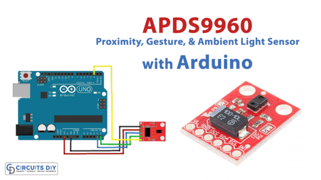 APDS9960 Proximity, Gesture, and Ambient Light Sensor Interfacing with Arduino
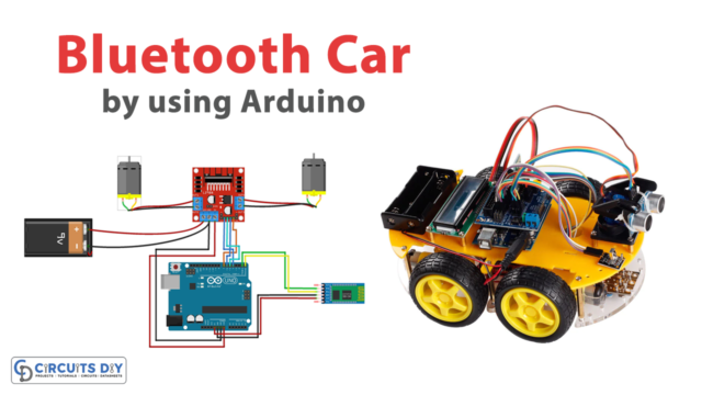 Arduino Bluetooth Car
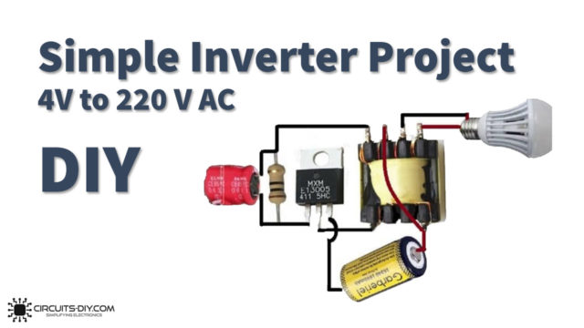 4V DC to 220V Simple Inverter Project using MJE13005
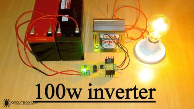 100 Watts Inverter Circuit using CD4047 & IRF540
 Interfacing 1.8 Inch SPI TFT Color Display Module with Arduino
 Control Stepper Motor with L293D Motor Driver IC & Arduino


