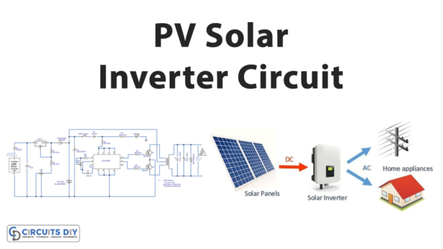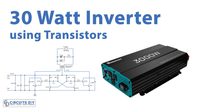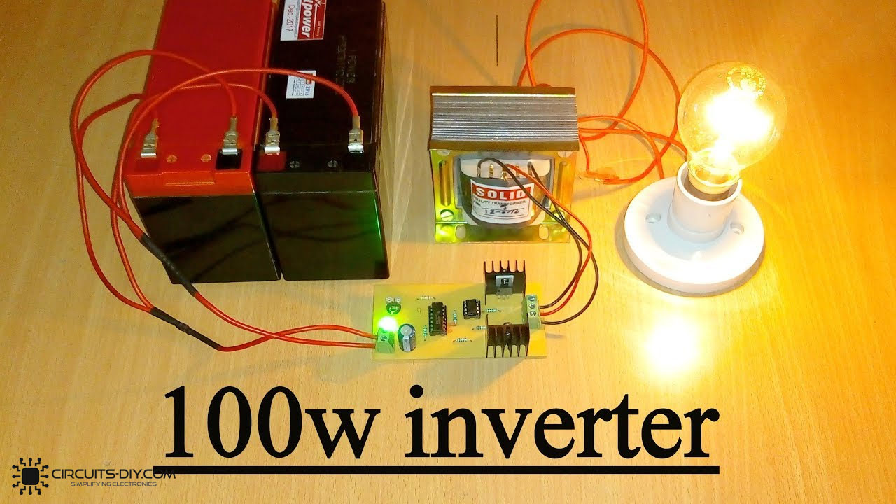
If you’re a complete beginner to electronics, know that an inverter is a circuit that is designed to convert the direct current (DC) power to alternating current (AC) power. In simpler words, the basic function of the inverter circuit is to generate the oscillation. Inverters can be of different types and can be made in different ways. Also, different inverters generate different watts of power at the output. Hence, we are making 100 watts inverter circuit in this article.
You may get confused that how it works. Let’s understand this more quickly. Suppose you have a DC battery. Connect that battery with the MOSFET driver circuit, this will create oscillations. Now, these oscillations are not that feasible to use with AC appliances. So, now you need a transformer for that. This transformer will boost the signal and at them out, you will get the AC power.

Hardware Required
| S.no | Component | Value | Qty |
|---|---|---|---|
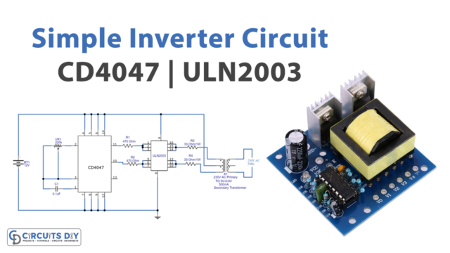
| 1. | IC | CD4047 | 1 |
| 2. | MOSFET | IRF540 | 2 |
| 3. | Resistor | 330 ohm, 220 ohm, 1k ohm, 390k ohm | 1, 2, 2, 1 |
| 4. | Diode | 1N4007 | 1 |
| 5. | Switch | – | 1 |
| 6. | Capacitor | 0.01uF, 0.1uF | 1, 1 |
| 7. | Transformer | 150VA | 1 |
| 8. | Battery | 12V | 1 |
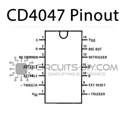
CD4047 IC Pinout
IRF540 Pinout

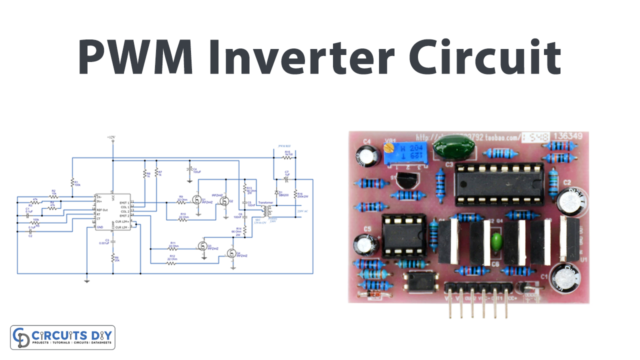
Circuit Diagram
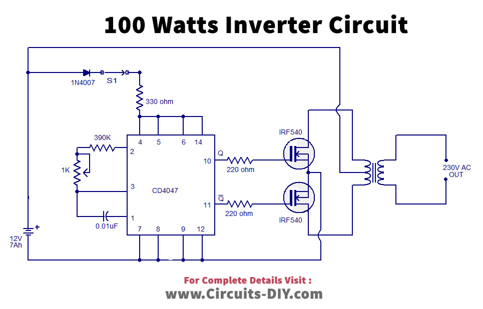
Working Explanation
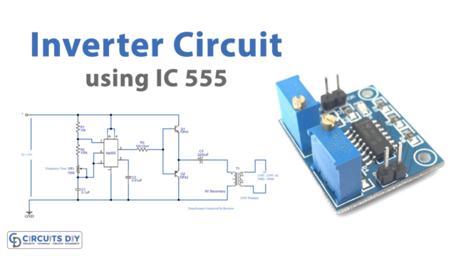
The circuit uses the CD4047 IC which works can work in astable or monostable mode. Basically, CD4047 is the 14 pin IC with having very low power consumption. The only purpose of this IC in the circuit is to generate a duty cycle of 50%. To drive the output coming from an Ic, two IRF540 MOSFETs are used. Since the Mosfet is a high switching transistor, needs low gate power for division and has high impedance. Therefore, preferable to use. At the final stage, the transformer steps up the oscillation and provides it at the output to use.
Applications
- One good example is the UPS which is pretty much used by everyone.
- The electric motor is another example.
- Also, it is used in solar circuits.
- Refrigerator, etc.