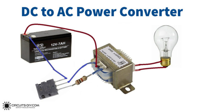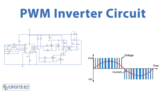
In this tutorial, we are going to make a “Simple Inverter Circuit using CD4047 and ULN2003”. A power inverter is a power electronic device or circuitry, that changes direct current (DC) to alternating current (AC). The resulting AC frequency obtained depends on the particular device employed. The input voltage, output voltage and frequency, and overall power handling depend on the design of the specific device or circuitry. The inverter does not produce any power; it is provided by the DC source. As Inverter circuits provide AC power output using available DC voltage from the battery. Sometimes we need low power output enough, to drive a small electric light bulb or something those are not required pure AC power. Here we design a simple inverter circuit, in order to avoid complex pure sine wave inverters and PWM inverters for low-voltage applications.
Hardware Required
| S.no | Component | Value | Qty |
|---|---|---|---|
| 1. | IC | CD4047 | 1 |
| 2. | IC | ULN2003 | 1 |
| 3. | Resistor | 470Ω,33Ω | 2,2 |
| 4. | Capacitor | 0.1uf | 1 |
| 5. | Variable Resistor | 220KΩ | 1 |
| 6. | Transformer | 9V-0-9V | 1 |
| 7. | Connecting Wires | – | – |
| 8. | Battery | 12V | 1 |
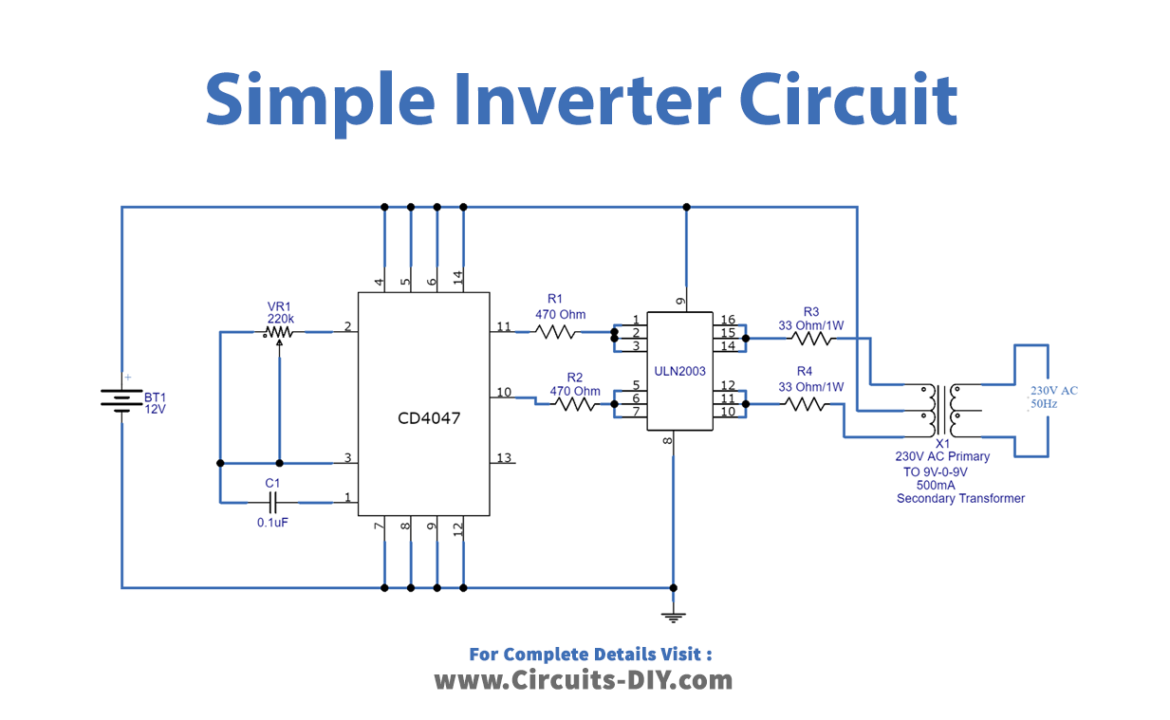
Circuit Diagram
IC ULN2003 Pinout
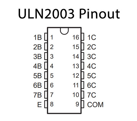
Working Explanation
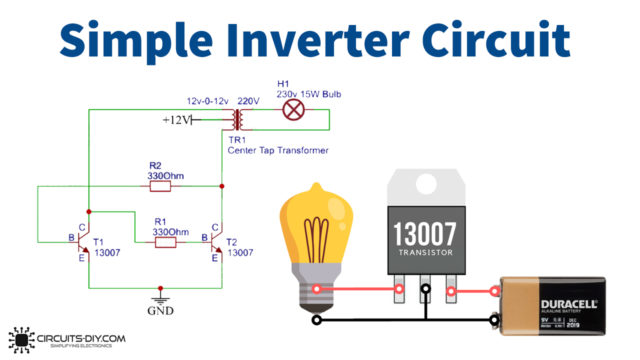
As we can see in the circuit, it has three simple stages. In the first stage, we designed a multivibrator by using IC CD404. It produces a free-running astable pulse with high peak voltages. And then the second stage is the power switching stage, in which we have used IC ULN2003 (Seven Darlington array). It handles a 500mA current and is best suitable for inductive load driving. Now a group of three channels is connected in (Q bar pin 11) and (Q pin 10) output of CD4047. Output from ULN2003 is connected to the transformer X1 secondary winding (9V – 0 – 9V), and the center-tapped pin is connected to the 12V supply. Transformer primary winding provides step-up pulsating AC (load is connected between the primary winding terminals). To simplify the design, there is no switch, fuse, or MOV (metal oxide varistor). We can change the frequency and voltage range of the output AC supply by varying the VR1 resistor value. Handle with extreme care this circuit, as it is involved in producing high AC Voltage that may give a lethal shock.
Applications
- They are utilized in solar power systems
- An inverter is the basic building block for SMPS – switch mode power supply.
- Can be used by devices such as centrifugal fans, pumps, mixers, extruders, test stands, conveyors, metering pumps, and web-handling equipment.