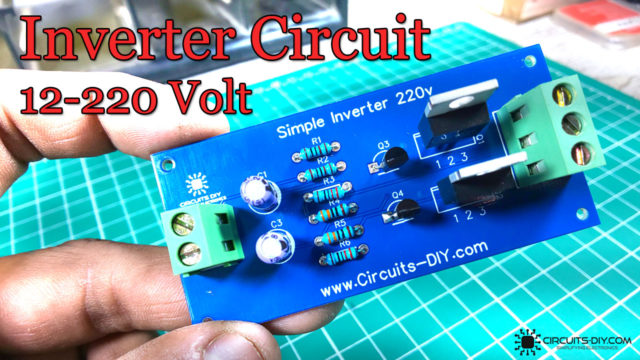
Introduction
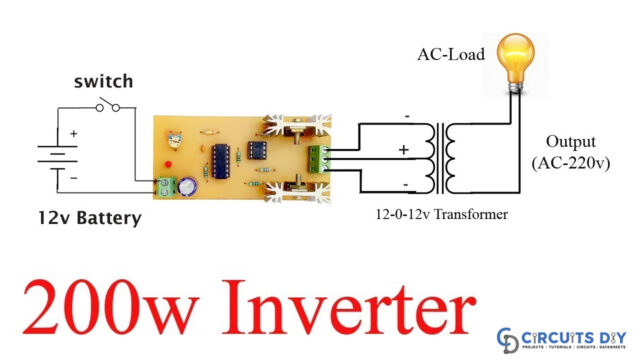
There are several ways to create an inverter when an engineer needs to convert DC to AC electricity. So we decided to attempt creating an inverter out of a 12-volt battery. We can achieve 220V AC at the output of just 12 volts. As a result, the circuit may require a large number of components to enhance the voltage. No, the circuit is so basic that just a few components are required. But how do you do it? We’ll find out the answer to this question as we work our way through the circuit. As a result, in this tutorial, we will see How to make an Inverter Circuit.
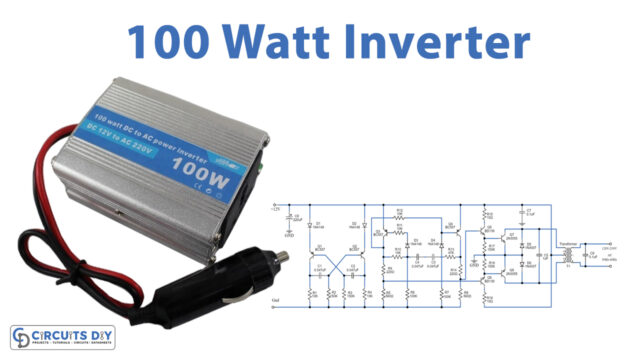
An inverter’s primary function is to convert DC electricity to AC power. The public utility can provide AC electricity to houses and companies; the alternating-power systems or circuits of the batteries only store DC power. Furthermore, practically all everyday appliances, as well as other electrical equipment, can be operated with AC power.
Get a $50 coupon for your PCB&PCBA Order: From fabrication to assembly, and from 1 layer to 14 layers, PCBGOGO is experienced enough to meet all your needs. Prototyping PCB at PCBGOGO now, try it.
Hardware Components
The following components are required to make the Inverter Circuit
| S.no | Component | Value | Qty |
|---|---|---|---|
| 1. | IC | CD4047 | 1 |
| 2. | MOSFET | IRFZ44 | 2 |
| 3. | Center tapped transformer | 12-0-12V | 1 |
| 4. | Potentiometer | 100KΩ | 1 |
| 5. | LED | – | 1 |
| 6. | Capacitor | 1000µF, 10nf | 1 |
| 7. | Resistor | 300k, 1k, 220 | 1, 1, 2 |
| 8. | Power Supply | 12V | 1 |
CD4047 Pinout

For a detailed description of pinout, dimension features, and specifications download the datasheet of CD4047
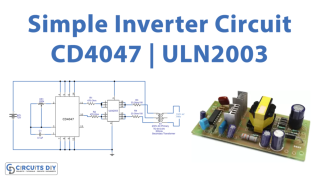
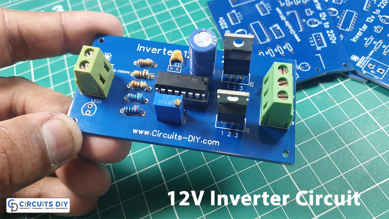
Inverter Circuit
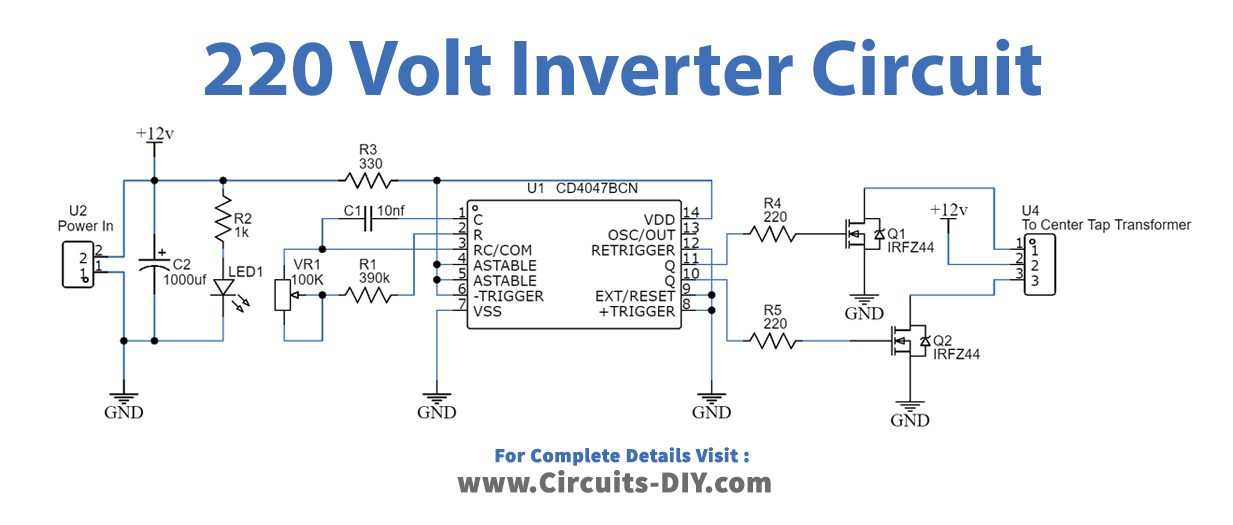
Working Explanation
The CD 4047 IC is configured in this 12 Volt to 220 Volt Inverter with the aid of several components like the potentiometer, capacitors, and resistors. Pins 10 and 11 are used to collect the output. You may acquire a variable range of output pulse at pin 10 Q and pin 11 Q’ pins by adjusting the value of the Variable Resistor. The N channel MOSFETs, whose drain pins are coupled to the transformer, receive this output. When the wired MOSFETs are driven with alternating square pulses, the secondary winding is pushed to create an alternative magnetic field. This magnetic field is now induced in the transformer’s main winding, resulting in a high alternate voltage.
Application and Uses
- For any AC circuits requiring low DC voltage conversion
- This circuit can also be used by lighting systems.
- You can use this in different indication circuits that operate on AC power.