Introduction
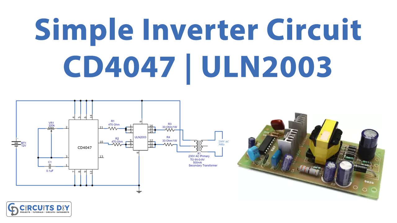
An inverter is an electrical device used to convert direct current (DC) voltage to alternating current (AC) voltage in common appliances is known as an inverter. Several tiny forms of equipment, such as solar power systems, are used in DC applications. An inverter’s primary function is to convert DC electricity to AC power. Practically all household appliances, as well as other electrical equipment, may be operated with AC power. So, in this tutorial, we are going to “Simple Inverter Circuit using CD4047 and ULN2003”
Features of CD4047
- Operate in both Monostable and Astable operation
- Require only a few external components that are one resistor and one capacitor
- Symmetrical buffered output characteristics
- High Noise Immunity
Features of ULN2003
- Contains 7 high-voltage and high-current Darlington pairs
- Each pair is rated for 50V and 500mA
- Input pins can be triggered by +5V
- All seven Output pins can be connected to gather to drive loads up to (7×500mA) ~3.5A
Hardware Required
| S.no | Component | Value | Qty |
|---|---|---|---|
| 1. | Darlington Transistor Array IC | ULN2003 | 1 |
| 2. | IC | CD4047 | 1 |
| 3. | Transformer | 9v | 1 |
| 4. | Potentiometer | 220KΩ | 1 |
| 5. | Capacitor | 0.1uF | 1 |
| 6. | Resistor | 33Ω, 470Ω | 2, 2 |
| 7. | Battery | – | 1 |
| 8. | 2-Pin Connector | – | 1 |
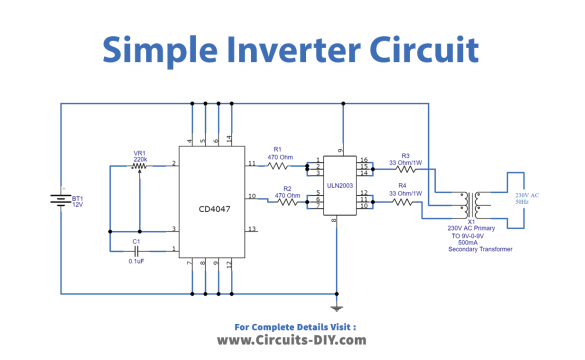
Circuit Diagram
Working Explanation
This Simple Inverter Circuit using CD4047 and ULN2003 has two stages. The first stage is a multivibrator stage, which uses the IC CD4047 to generate a free-running astable pulse with high peak voltages. The second stage is a power switching stage, which uses the IC ULN2003 to handle a 500mA current and is best suited for inductive load driving.
A set of three channels is wired to the CD4047’s pin 11 and pin10) outputs. The ULN2003 output is linked to the secondary winding of the transformer, and the center-tapped pin is connected to the 12V supply. Pulsating AC is provided by the primary winding of the transformer (load is connected between the primary winding terminals). The potentiometer is there in the circuit to change the frequency and voltage range of output.
Application and Uses
- It may be used to run AC appliances.
- This easy project may be used to control the AC lights or a light bulb.
- We may utilize it in power supplies, UPS circuits, and other applications with simple modifications.