Introduction
Every person’s voice is unique and distinct. Often, we can recognize someone’s identity by their voice alone, without even seeing them. But what if you could modify the tone of a person’s voice and make it sound like someone else or something out of this world? Modifying our voices is not new, but technological advancements have made it easier. In this blog post, we will explore the world of digital voice changers and learn how to make a simple yet effective circuit that can transform your voice into something unique.
If you are interested in technology and want to try your hand at building a digital voice changer circuit, this blog post is the perfect place to start.
Hardware Required
| S no | Components | Value | Qty |
|---|---|---|---|
| 1 | IC1 IC2 | HT8950A LM386 | 1 1 |
| 2 | Zener Diode | 6.2V | 1 |
| 3 | Resistor | 100k, 47k, 39k, 4.7k, 8.2k, 470k, | 1, 1, 1, 3, 1, 1 |
| 4 | V. Resistor | 5k | 1 |
| 5 | Polar Capacitor | 220u, 47u, | 3, 1 |
| 6 | Non Polar Capacitor | 0.1uF 0.47uF | 2 1 |
| 7 | MIC | Electret Mic | 1 |
| 8 | Switch | – | 4 |
| 9 | Speaker | 8 ohm | 1 |
| 10 | Battery | 9V | 1 |
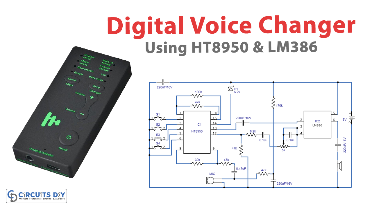
Circuit Diagram
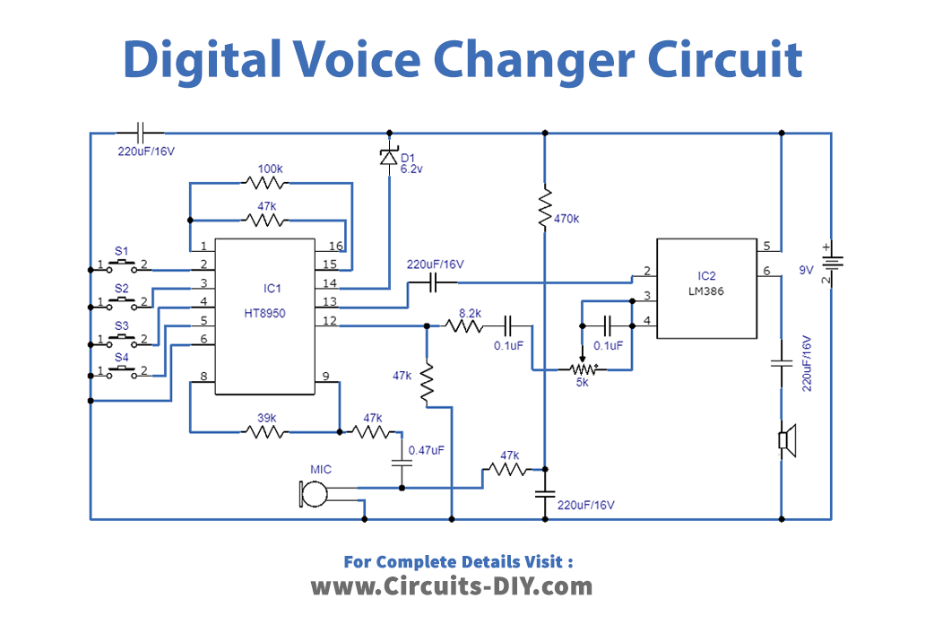
The schematic diagram of the digital voice changer includes an amplifier, A/D and D/A converters, static RAM, and an audio amplifier. The user’s voice is captured by an electret microphone and fed to the internal amplifier. The voice signal is then digitized, stored in a static RAM, and transferred to a latching register. Finally, the speech signal goes to a D/A converter, where it is reset to its original analog form or shifted frequency spectrum. The speech signal is then transmitted through a network to an audio amplifier and then to the speaker, making it audible.
Function Of Each Pin Of HT8950A
The table below summarizes the function of each pin for the HT8950A version:
| Pin No. | Pin Name | Function |
|---|---|---|
| 1 | OSC1 | Input of the oscillator |
| 2 | VIB | Input mode selector for vibrato |
| 3 | TGU | Step input selector for up |
| 4 | TGD | Input selector for step down |
| 5 | ROB | Input selector mode for robot |
| 6 | VSS | Negative supply line (GND) |
| 7 | NC | Not connected |
| 8 | A0 | Output of internal amplifier |
| 9 | AIN | Input of the internal amplifier |
| 10 | VDD | Positive power line |
| 11 | LED | Output for volume lamp |
| 12 | AUDIO | Audio output |
| 13 | VREF | Reference voltage for the internal amplifier |
| 14 | TS | Chip test input |
| 15 | FVIB | Control output frequency for vibrato |
| 16 | OSC2 | Output of the oscillator |
Working Explanation
The digital voice changer circuit utilizes a voice modulator technology from HOLTEK that digitally processes the incoming voice signal. By shifting the frequency spectrum of the voice signal in seven incremental steps, the output is transformed to sound thicker or thinner in frequency.
Voice Modulation: This process is similar to changing the playback speed of a recorded voice on tape, except that it does not distort the speech or affect its speed. In addition, the circuit adds two sound effects: vibrato and robot, which can convert the voice into a tremulous or robotic one.
Input and Output: An electret microphone picks up the voice input, and the output is played through a dynamic speaker. The entire system operates on a 9V battery.
Conclusion
Making a digital voice changer circuit can be a fun and rewarding do-it-yourself project for people interested in electronics and changing sounds. You can build a device that changes voice by following the steps outlined in this article. The possibilities are endless, whether you want to use it for practical purposes or just for fun. We hope you found this article helpful and enjoyable, and we wish you luck in your digital voice changer circuit-building endeavors!