Smoke ventilation systems, are designed to effectively remove smoke, heat, and combustion products from the areas affected by the fire. Here while soldering, we all face the problem of toxic fumes. These fumes are of lead solder wire and flux. Combined, these fumes are highly toxic if an excess amount is inhaled. Hence Soldering is an art in electronics, when we solder components in PCB or dot board it produces smoke and fumes which is toxic and dangerous to human health. To solve this problem, here we designed a simple circuit called a solder smoke extractor with easily available components.
Hardware Required
| S.no | Component | Value | Qty |
|---|---|---|---|
| 1. | BiMOS Operational Amplifier | CA3130 | 1 |
| 2. | Transistor | BC547 | 1 |
| 3. | Transistor | BD139 | 1 |
| 4. | Diode | 1N4007 | 2 |
| 5. | Resistor | 100KΩ,1KΩ | 2,2 |
| 6. | Capacitor | 470uF | 1 |
| 7. | LED | – | 1 |
| 8. | Fan CON2 | 6V | 1 |
| 9. | On/Off Switch | – | 1 |
| 10. | Variable Resistor | 10KΩ | 1 |
| 11. | Connecting Wires | – | – |
| 12. | Rechargeable Battery | 6V 4.5 Ah | 1 |
| 13. | Piezo Element | – |
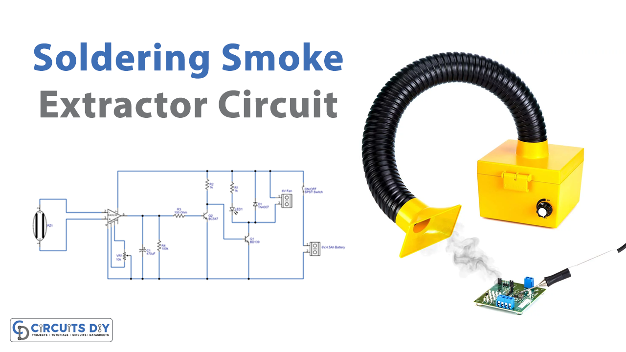
Circuit Diagram

Working Explanation
As we can see in the circuit, a 6V DC fan works as a smoke and fumes exhaust device. When we solder components this fan started to run. Here to provide bias the 6V 4.5 Ah rechargeable battery is used. If you have a workbench then you can use a DC power source. To produce electrical difference due to heat from soldering iron the piezo element is placed, and for safety make a heatsink on the piezo element.
Now BiMOS operational amplifier CA3130 is connected with the piezo element through inverting and non-inverting terminals. Here the variable resistor VR1 is used to vary the offset. Further, the output from the operational amplifier is connected to the transistor Q2 BC547 and directed to the BD139 bi-junction transistor. In the end, the output indicator LED and 6V fan followed through +Vcc connected in the collector terminal of BD139.
Applications
Can be used in electronics labs.