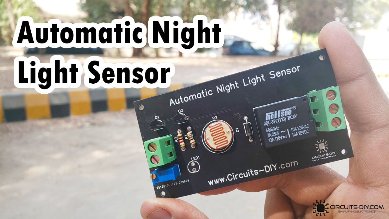
What is an Automatic Night Light Sensor?
An automatic night light sensor is an electronic device that is capable of sensing the light sensitivity in the surrounding area & determines whether it’s day or night. If it’s night, it switches ON the associated circuit & turns OFF in case it’s daytime. So, in this tutorial, we are going to go through a step-by-step procedure on How to make an Automatic Night Light Sensor Using BC547 Transistors.
The main component of this circuit is an LDR or a light-dependent resistor. An LDR is basically a photocell that works on the principle of photoconductivity. This passive component is basically a resistor whose resistance value decreases when the intensity of light decreases.

PCBWay commits to meeting the needs of its customers from different industries in terms of quality, delivery, cost-effectiveness, and any other demanding requests. As one of the most experienced PCB manufacturers in China. They pride themselves to be your best business partners as well as good friends in every aspect of your PCB needs.
Hardware Components
The following components are required to make Automatic Night Light Sensor Circuit
| S.no | Component | Value | Qty |
|---|---|---|---|
| 1. | Relay | SPDT/5V | 1 |
| 2. | LDR | 5mm/2mm/ | 1 |
| 3. | Transistor | BC547 | 2 |
| 4. | LED | 5mm/3.5V | 1 |
| 5. | Variable Resistor | 10K | 1 |
| 6. | Diode | 1N4007 | 1 |
| 7. | Resistors | 100 Ohm, 1K | 1 |
| 8. | Soldering Iron | 45W – 65W | 1 |
| 9. | Soldering wire with flux | – | 1 |
| 10. | Veroboard | – | 1 |
| 11. | DC Battery | 9V | 1 |
| 12. | Battery clips | – | 1 |
| 13. | Jumper Wires | – | As per need |
BC547 Pinout

For a detailed description of pinout, dimension features, and specifications download the datasheet of BC547
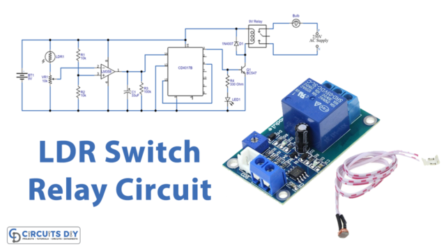
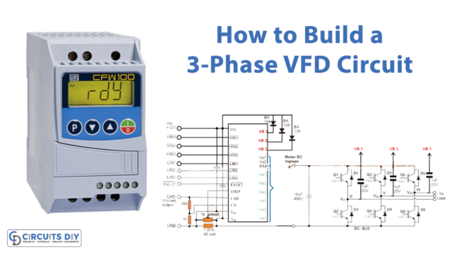
Automatic Night Light Sensor Circuit

Working Explanation
The working of this circuit is pretty simple, during the daytime the resistance of the LDR is pretty high, blocking any meaningful control signal to go through the base of the first BC547 transistor. As soon as night falls, the resistance of the LDR rapidly decreases, causing a control signal to flow through the base of the first transistor.
The collector output of the first transistor serves as the control signal for the second transistor. The subsequent collector output energizes the coil of the 5V SPDT Relay, which makes the external circuit, connected across the COM & NC terminal of the relay. Always use an SPDT relay with a voltage rating comparable to the input power supply (12V/9V/5V).
Applications
- It can be used to activate outdoor lights at night-time like garden lamps, night lights, etc.