Introduction
Darkness scares most of us, and who knows, maybe that was the reason that light got invented. But, today our topic is not about light but the dark. The darkness detector sensor. But, the question arises where do we need a detector that senses dark? See, we humans are trying every day to get an automated world, we love to don’t spend our time on various little things that distract us from doing other great work. For instance, take an example of street lights, to turn on those lights manually, requires someone to do that duty every single day. But, on the other hand, if we make this automated by using a dark sensor so that it detected the darkness and turns on automatically, this would save our time. So, in this tutorial, we are going to “Darkness Detector Circuit”

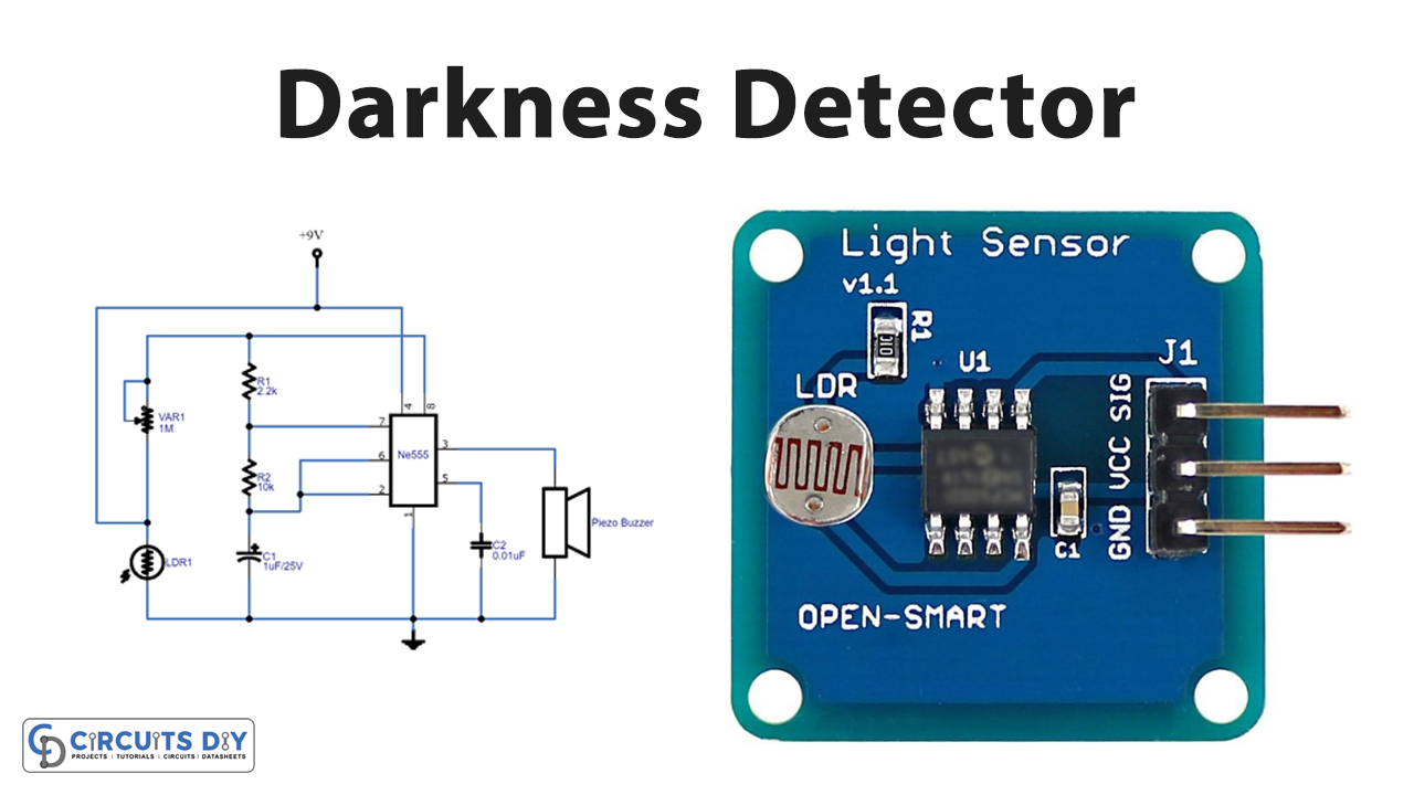
Hardware Components
The following components are required to make Darkness Detector Circuit
| S.no | Component | Value | Qty |
|---|---|---|---|
| 1. | LDR (Any size) | – | 1 |
| 2. | IC | NE555 Timer | 1 |
| 3. | Piezo buzzer | – | 1 |
| 4. | Potentiometer | 1MΩ | 1 |
| 5. | Capacitor | 1uF/25V, 0.01uF | 1,1 |
| 6. | Resistor | 2.2KΩ, 10KΩ | 1,1 |
| 7. | Connecting wires | – | – |
| 8. | Battery | 9V | 1 |
| 9. | Connector | 2-Pin | 1 |
NE555 IC Pinout

For a detailed description of pinout, dimension features, and specifications download the datasheet of 555 Timer
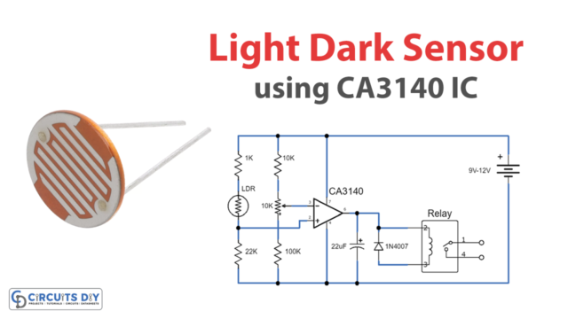
Darkness Detector Circuit
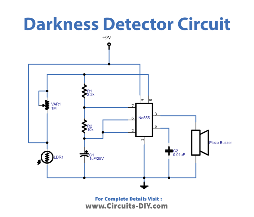
Working Explanation
In this Darkness detector circuit, the 555 timers IC is working as a stable multivibrator circuit. There is a variable resistor in the circuit through which we can change the sensitivity. When there is a constant light falling on the LDR, there is no current flow through the circuit. Whenever something occurs between the light and LDR, the LDR detects the darkness and decreases its resistance. In that case, the current starts flowing through the circuit. As a result, the buzzer beeps.
Application and Uses
- Automatic street lights.
- Burglar and intruder alarms.
- Night lamps, etc