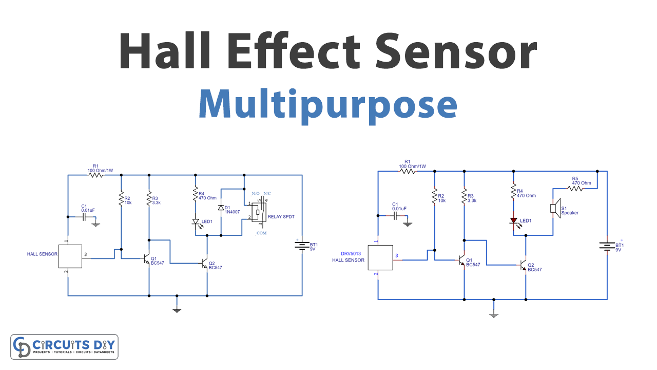
In this tutorial, we are going to make a “Multipurpose Hall Effect Sensor Circuit”. There are so many sensors and transducers available in the market, to check the practical behavior of any electrical or electronic equipment. Because it is necessary to install a device that communicates between electrical or electronic equipment and a real-time system. Here Hall effect sensor is the type of sensor, which is typically used for detecting the practical behavior of different equipment. Such as the motor in response to changing magnetic field (This sensor reacts to the magnetic field and changes its output which depends on the polarity of the magnet and magnetic field strength).
In simple words, it just works like an analog transducer. They are mainly used for speed detection, approximate switching, current, and positioning sensing applications. Here we use a DRV5013 Hall Effect sensor from texas instruments, it is a digital latch Hall effect sensor. It operates with wide voltage ranges (2.5 to 38V) and provides bipolar switching. This sensor has reverse supply protection up to -22 volts and also outputs short circuit protection with current limitation features. The DRV5013 is available in through-hole and surface.
Hardware Required
| S.no | Component | Value | Qty |
|---|---|---|---|
| 1. | Hall Effect Sensor IC | DRV5013 | 1 |
| 2. | SPDT Relay | – | 1 |
| 3. | Transistor | BC547 | 2 |
| 4. | Diode | 1N4007 | 1 |
| 5. | Resistor | 10KΩ,3.3KΩ,100Ω/1W,470Ω | 1,1,1,2 |
| 6. | LED | – | 1 |
| 7. | Capacitor | 0.01uf | 1 |
| 8. | Connecting Wires | – | – |
| 9. | Buzzer | – | 1 |
| 10. | Battery | 9V | 1 |
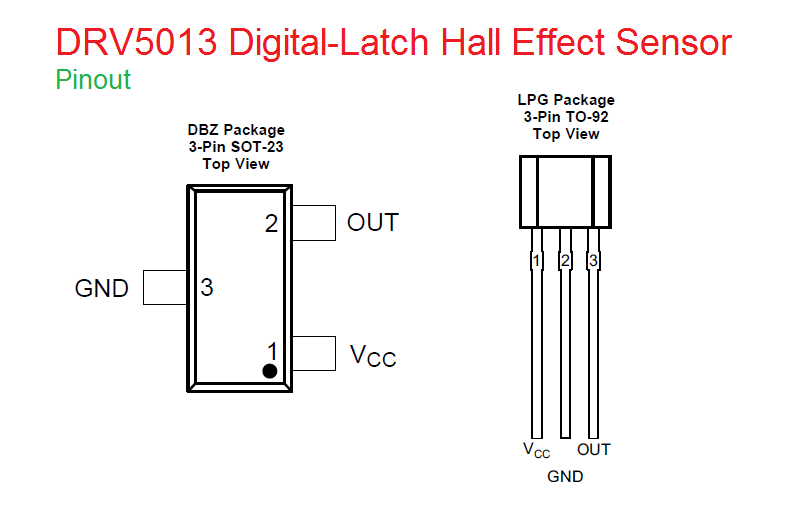
DRV5013 Pinout
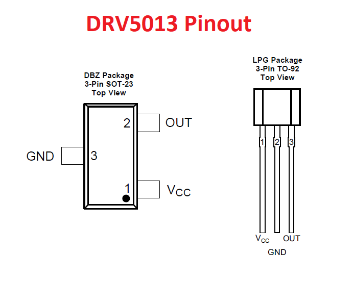
The DRV5013 device is a chopper-stabilized Hall effect sensor, that offers a magnetic sensing solution with superior sensitivity stability over temperature and integrated protection features. It can easily be implemented in the design of handheld electric tools, as it has only three pins and is fabricated in small size. Here make sure to position the magnet’s south pole to face the sensor. Because the output state of this sensor depends on the magnetic field perpendicular to the package, the South Pole near the front side (The marked side of the package) causes the output to pull low. Now in this article, two different application circuits are designed based on DRV5013. It can be modified to any magnetic sensing & switch or alarm circuit (Multipurpose…).
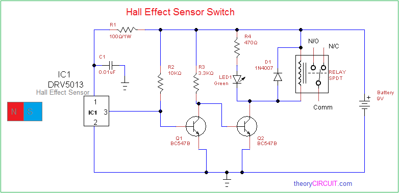
1. Hall Effect Sensor Switch
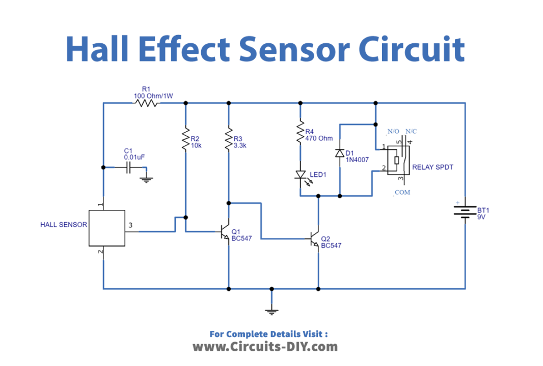
Hall effect sensor is basically transducers whose voltages vary by changing magnetic field. This sensor consists of a metal strip when it is placed inside any magnetic field. The presence of this magnetic field electron is deflected towards the edges of this strip, then EMS is induced across its edges. In this circuit, any load can be controlled depending on the hall sensor output. Here at the output stage of the Hall sensor, an SPDT relay is connected. When the magnet South Pole appears near DRV5013, then the output becomes low. Due to this low output Q1 transistor become open. Hence the +ve supply reaches the Q2 transistor base through the R3 resistor. Q2 transistor becomes closed when the base bias appears. Then the LED and relay get supply and come to turn ON state.
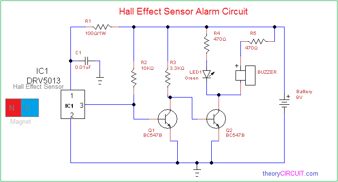
2. Hall Effect Sensor Alarm Circuit

In this circuit, a buzzer is placed at the output stage to give an alert sound, although the working principle is the same as in the previous circuit. Here this circuit can be used as a door open alarm, desk drawer open alarm, object alarm, etc.…
Applications
- Power tools
- Valve and solenoid status
- Brushless dc motors
- Proximity sensing
- Tachometers


