The light fence circuit is used to detect the presence of any person or object in a specific area. The Light Fence Circuit detection range is around 1.5 to 3 meters. Designing the circuit using LDR and Op-amp is fairly simple. This portable circuit will operate easily with a commonly accessible 9V battery, and the buzzer-generated warning sound is loud enough to detect a person, car, or object.

Hardware Required
The following components are required to make an Automatic Light Fence Circuit
| S.no | Component | Value | Qty |
|---|---|---|---|
| 1. | Resistor | 210, 1K, 5.7K, 100k, 1M | 1, 1, 1, 1, 1 |
| 2. | Capacitor | 0.1uf, 10uf | 1, 1 |
| 3. | LDR | – | 1 |
| 4. | Op-amp IC | LM741 | 1 |
| 5. | Transistor | BC557 | 1 |
| 6. | IC | NE555 timer | 1 |
| 7. | Potentiometer | 100K | 1 |
| 8. | Buzzer | – | 1 |
| 9. | LED | – | 1 |
| 10. | Breadboard | – | 1 |
| 11. | Battery | 9V | 1 |
NE555 IC Pinout

For a detailed description of pinout, dimension features, and specifications download the datasheet of 555 Timer
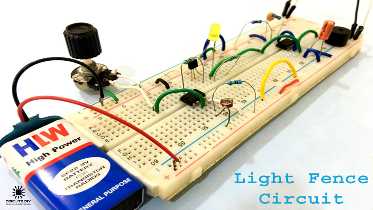
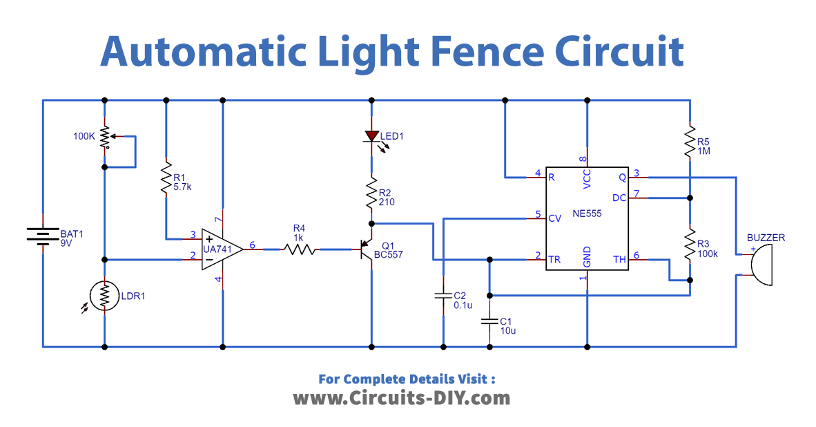
Automatic Light Fence Circuit
Working Explanation
This circuit can run using a 9-volt battery. The op-amp IC is used as a voltage comparator in the circuit, and the 555 timer IC is put in an astable mode. A voltage divider circuit is generated by the LDR and the potentiometer. This divider circuit’s output can vary based on the amount of light falling on the LDR. The divider is attached to the Op-amp IC inverting plate. A 5.7K ohm resistor binds the non-inverting pin with the source, and the voltage value at the non-inverting is set.
To change the voltage according to the necessity you should substitute this resistor with a 10 K potentiometer. Whenever a human or entity approaches a forbidden place, the LDR detects the shadows and the circuit activates an alarm. The sensitivity of the device can be adjusted by using the potentiometer in series with the LDR
Application and Uses
- The light fence circuit is used to detect the presence in a specific area of any person or entity