Introduction
A security alarm for intruders may definitely make you feel more at ease and help you sleep better if you don’t live in a particularly secure area. You need to have an intruder alarm so that you can defend your house and belongings from burglary and invasion. If someone tries to enter your house, that alarm will notify you, your neighbors, and potentially the authorities. Motion detection sensors are typically used in these burglar and security alarms, and this is the main topic of this article.
Thus, we are only trying to make a small prototype explaining those alarms. Continue reading this article, and you will be able to make the coolest motion detection sensor RCWL-0516 radar sensor.
What is Motion Detection?
Motion detection represents a system’s capacity to detect movement and notify the user. Motion detection often involves a monitoring device that alerts the system when it notices movement.
Hardware Components
You will require the following hardware for Motion Detection Sensor.
| S.no | Component | Value | Qty |
|---|---|---|---|
| 1. | Arduino UNO | – | 1 |
| 2. | RCWL-Sensor | 0516 | 1 |
| 3. | Resistor | – | 1 |
| 4. | Breadboard | – | 1 |
| 5. | Jumper Wires | – | 1 |
Steps for Making a Motion Detection Sensor
In this motion detection sensor, we will use only a few simple electronic components. Once you have those components, proceed as follows:
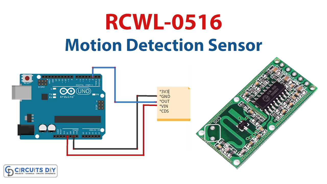
Schematic
Make connections according to the circuit diagram given below.

Wiring / Connections
| Arduino | RCWL-0516 Sensor |
|---|---|
| 5V | VIN |
| GND | GND |
| D2 | OUT |

Installing Arduino IDE
First, you need to install Arduino IDE Software from its official website Arduino. Here is a simple step-by-step guide on “How to install Arduino IDE“.
Code
Now copy the following code and upload it to Arduino IDE Software.
#define SensorPin 2
#define LedPin 13

void setup() {
  // put your setup code here, to run once:
  pinMode(SensorPin, INPUT);
  pinMode(LedPin, OUTPUT);

}

void loop() {

    // put your main code here, to run repeatedly:
    int sensorValue = digitalRead(SensorPin);
    if(sensorValue == HIGH){
    digitalWrite(LedPin, HIGH);
    }
    else{
    digitalWrite(LedPin, LOW);
    }
}
Let’s Test It
Now is the time to test the system! After uploading the code and powering on the Arduino, if you put something close to the circuit, the LED would turn on.
Working Explanation
Let’s understand the code to know how the circuit works:
- The code is quite basic. Arduino pins 2 and 13 are first described as sensor pins and LED pins, respectively.
- Then, we declare those pins’ state, or pin modes, in the void setup. The PIR pin is defined as the INPUT pin, while the LED pin is designated as the OUTPUT pin.
- The code then examines the value coming from the PIR pin and determines if it is HIGH. If it is, the LED is turned on; otherwise, it is left off.
Applications
- Home and workplace security systems
- Automatic doors
- Intruder alarms
Conclusion
We hope you have found this Motion Detection Sensor Circuit very useful. If you feel any difficulty in making it feel free to ask anything in the comment section.