In this tutorial, we are making an IR Remote tester circuit with an Alarm. There are a lot of devices around us that are controlled through IR remotes like TVs, media players, etc Different kinds of remote controls are available for different devices but most of them work on a frequency signal of approximately 38KHz. These remotes have a tendency to get faulty and we have to check multiple times if they are working properly, in these cases this remote tester can be useful.
This circuit has an IR Receiver sensor TSOP 1738 that has a FET signal amplifier and a PIN photodiode enclosed in an Epoxy case. For alarm purposes, we have used a melody-generating IC UM66.
Hardware Components
| S.no | Component | Value | Quantity |
|---|---|---|---|
| 1. | Input Supply DC | 6V | 1 |
| 2. | IR sensor | – | 1 |
| 3. | Transistor | 2N3906, BC548 | 1, 1 |
| 4. | IC | UM66 | 1 |
| 5. | LED | – | 1 |
| 6. | Zener Diode | 3V | 1 |
| 7. | speaker | 8 ohms | 1 |
| 8. | Diode | 1N4001 | 1 |
| 9. | Resistor | 1KΩ, 10KΩ, 100Ω, 47Ω | 1, 1, 3, 1 |
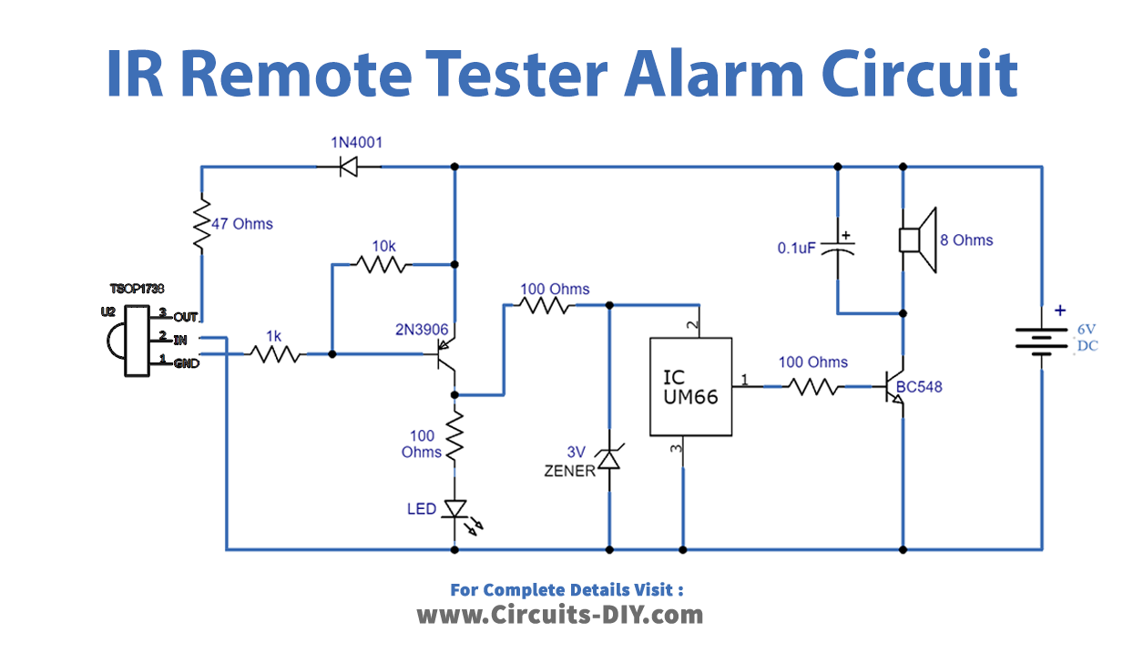
Circuit Diagram
Working Explanation
The operating voltage of this circuit is 6 volts DC. A TSOP1738 IR sensor is used to sense the IR signal. This detected infrared signal will go to the base of the transistor 2N3906. The transistor will now switch on and it will send a signal to LED and the UM66 IC. UM66 will generate the melody which is amplified by another transistor BC548. This amplified sound will drive an 8-ohm speaker.
A 3V Zener diode is used to step down the output voltage of the transistor 2N3906 to 3V to operate the IC. In this way, while testing the remote a visual indication through LED and an alarm can be heard when the remote is working properly.
Applications and Uses
It can be used to check the remotes of,
- TV
- Audio players
- DVD players
- AC, etc.