Overview
Measuring light intensity is a crucial aspect of various applications, from photography to environmental monitoring. A light meter provides an easy and accurate way to quantify light levels, helping photographers capture perfect shots and scientists gather valuable data
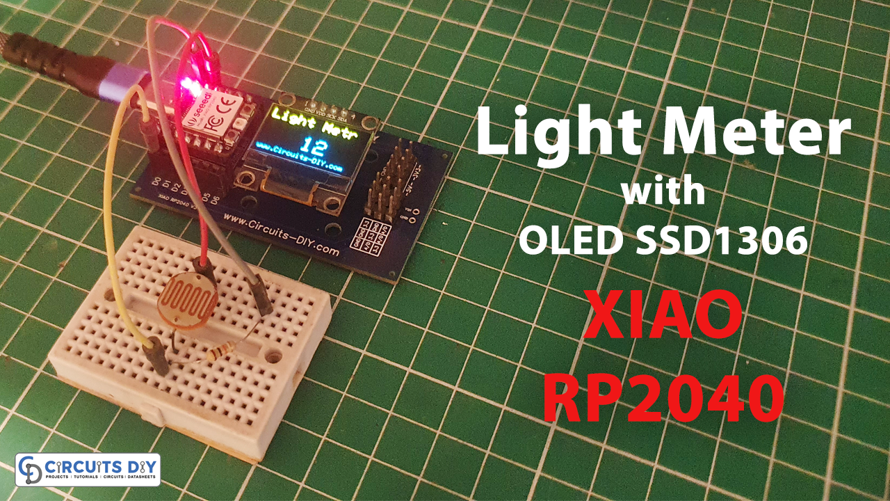
In today’s tutorial, we are going to make a “Light Meter” using the XIAO RP2040 Microcontroller & OLED SSD1306.
What is a Light Meter?
A light meter, also known as an exposure meter, is a device used to measure the intensity of light in a specific environment. Light meters typically provide readings in units like lux or foot-candles, which quantify the amount of illuminance or brightness at a particular location
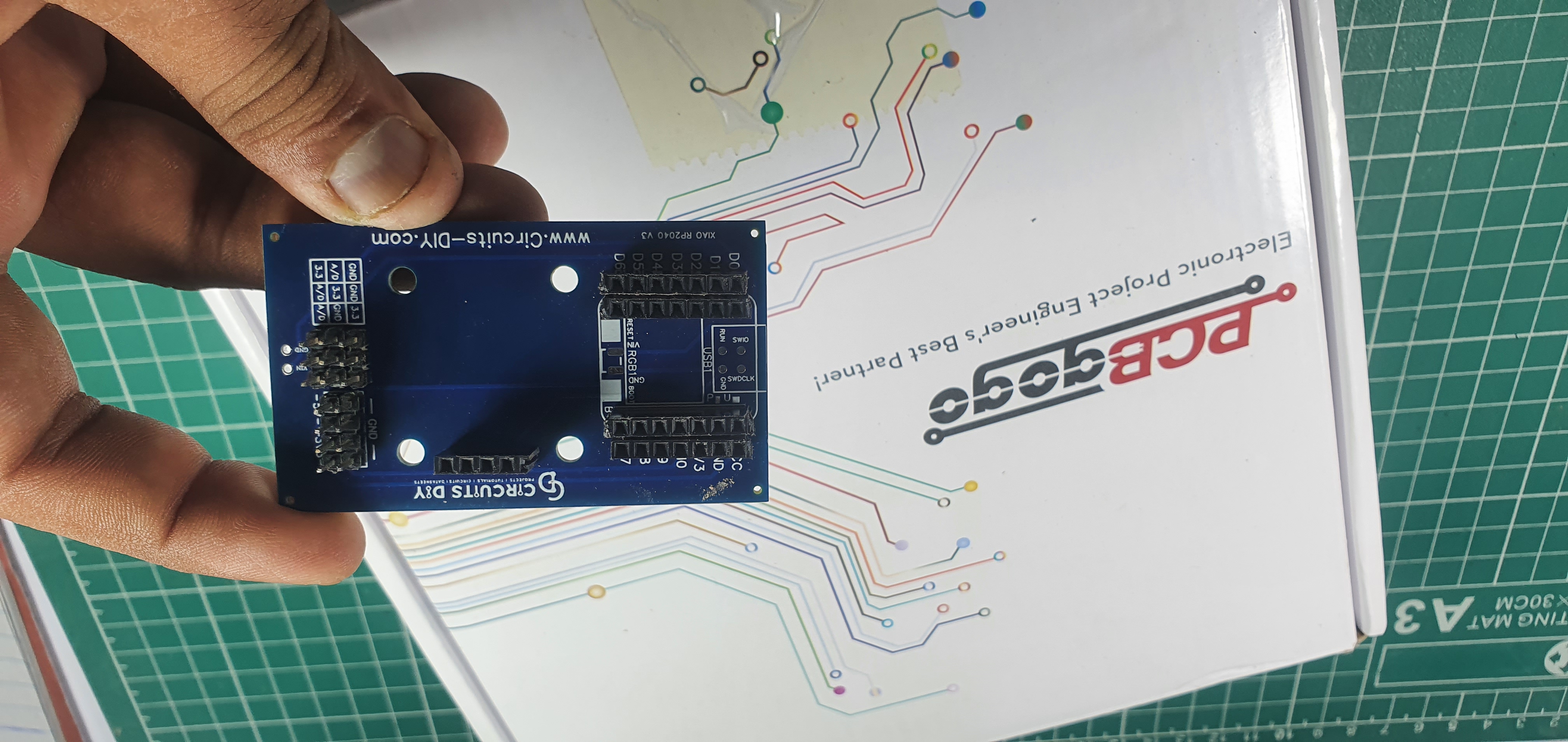
PCBGOGO has offered high-quality PCBs and the best PCB assembly service all over the world since 2015. Discover an incredible offer that puts PCB prototyping within reach for just $1. Yes, you read that right – for only a dollar, you can bring your innovative ideas to life with a PCB prototype. Don’t miss out on this fantastic opportunity to turn your electronics projects into reality. Explore the campaign here: PCBGOGO $1 PCB Prototype and pave the way for your next big creation!
Celebrate the 8th Anniversary with PCBGOGO and get up to $250 in coupons and lots of unexpected gifts https://www.pcbgogo.com/PCBGOGO_8th_year_celebration.html
Hardware Components
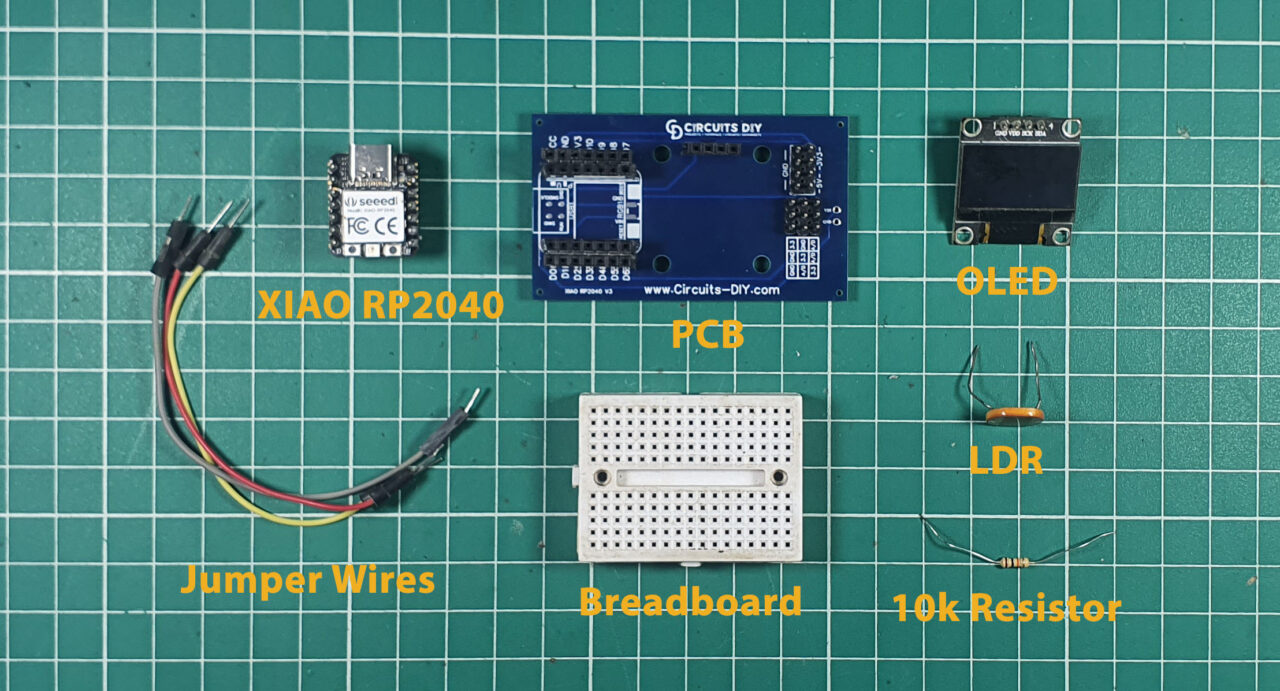
You’ll need the following hardware components to get started:
| Components | Value / Model | Qty |
|---|---|---|
| PCB | PCB-GOGO | |
| XIAO | RP2040 | 1 |
| OLED Display Module | SSD1306 | 1 |
| LDR | – | 1 |
| Resistor | 10kΩ | 1 |
| Jumper Wires | – | 1 |
XIAO RP2040 Pinout
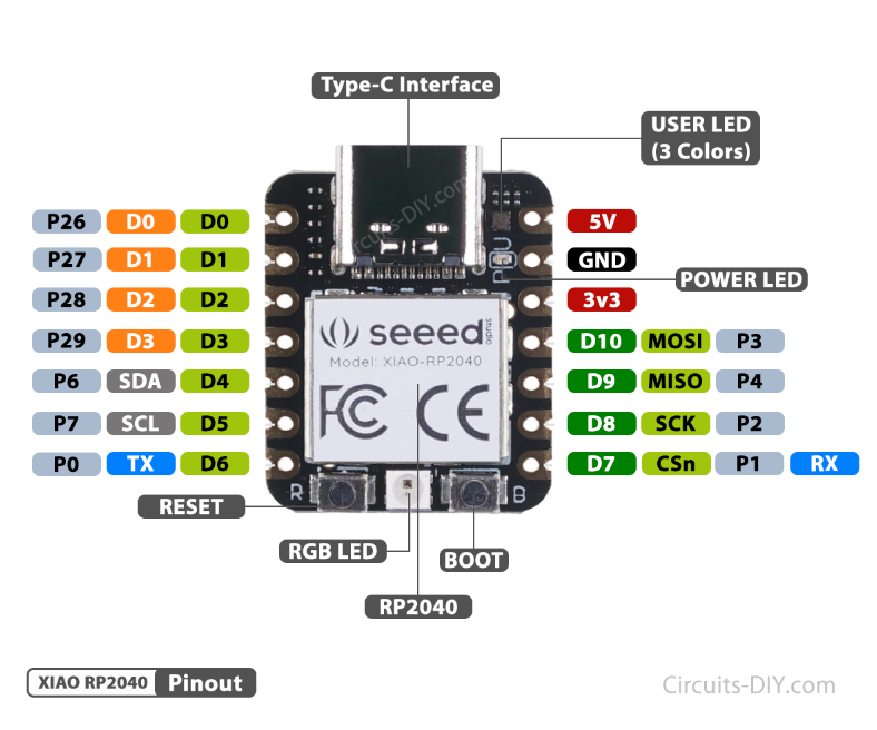
For details on the datasheet of the XIAO RP2040 Microcontroller visit this link.
| Pin No | Pin Name |
|---|---|
| 1 | P26 / A0 / D0 |
| 2 | P27 / A1 / D1 |
| 3 | P28 / A2 / D2 |
| 4 | P29 / A3 / D3 |
| 5 | P6 / SDA/ D4 |
| 6 | P7 / SCL / D5 |
| 7 | P0 / TX / D6 |
| 8 | P1 / RX / CSN / D7 |
| 9 | P2 / SCK / D8 |
| 10 | P3 / MISO / D9 |
| 11 | P4 / MOSI / D10 |
| 12 | 3V3 |
| 13 | GND |
| 14 | 5V |
SSD1306 OLED Display Pinout
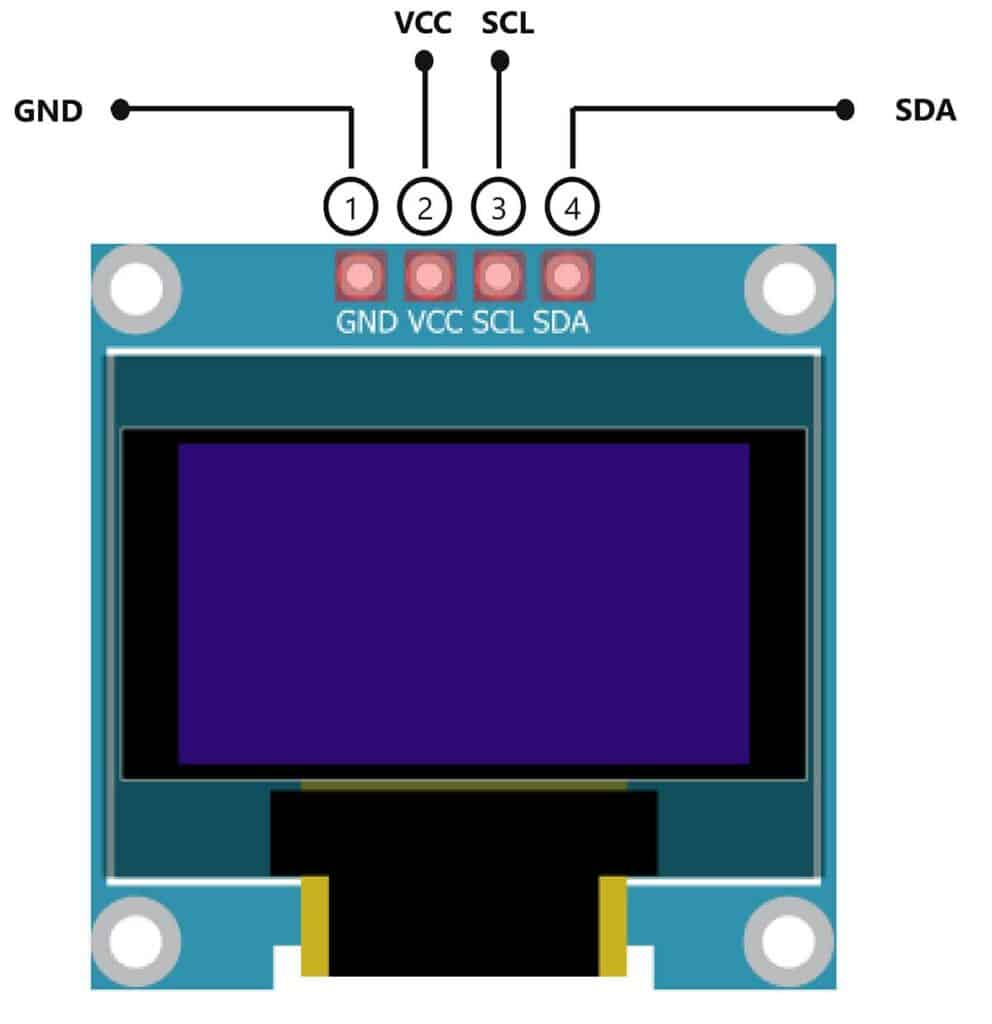
For details, on the datasheet of SSD1306 OLED Display Pinout visit this link.
| Pin No | Pin Name | Pin Description |
|---|---|---|
| 1 | VCC | VCC is the +5 volt Positive Pin |
| 2 | GND | GND is the (Ground) Negative |
| 3 | SCL | SCL is the Serial Clock Pin |
| 4 | SDA | SDA is the Serial Data Pin |
Steps-by-Step Guide
(1) Setting up Arduino IDE
Download Arduino IDE Software from its official site. Here is a step-by-step guide on “How to install Arduino IDE“.
(2) XIAO RP2040 in Arduino IDE
There’s an add-on that allows you to program the XIAO RP2040 using the Arduino IDE. Here is a step-by-step guide on “How to Install XIAO RP2040 on Arduino IDE“.
(3) Include Libraries
Before you start uploading a code, download and unzip the Wire.h, Adafruit_GFX.h, Adafruit_SSD1306.h library at /Program Files(x86)/Arduino/Libraries (default). Here is a step-by-step guide on “How to Add Libraries in Arduino IDE“.
(4) Schematic
Make connections according to the circuit diagram given below.
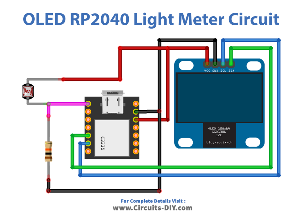
Wiring / Connections
| XIAO RP2040 | SSD1306 OLED Display | LDR & Resistor |
|---|---|---|
| 3.3V | VCC | LDR Terminal 2 |
| GND | GND | Resistor Terminal 1 |
| A5 | SCL | |
| A4 | SDA | |
| A0 | Resistor Terminal 2 + LDR Terminal 1 |
(5) Uploading Code
Now copy the following code and upload it to Arduino IDE Software.
/* Circuits DIY
 * For Complete Details Visit
 * https://www.circuits-diy.com/light-meter-using-xiao-rp2040-oled-ssd1306/
 */
#include <Wire.h>
#include <Adafruit_GFX.h>
#include <Adafruit_SSD1306.h>

#define SCREEN_WIDTH 128 // OLED display width, in pixels
#define SCREEN_HEIGHT 64 // OLED display height, in pixels
// Declaration for an SSD1306 display connected to I2C (SDA, SCL pins)
#define OLED_RESET     -1 // Reset pin # (or -1 if sharing Arduino reset pin)
Adafruit_SSD1306 display(SCREEN_WIDTH, SCREEN_HEIGHT, &Wire, OLED_RESET);
int LDR = A0;
int LDR_DATA;
int F_value; // LDR sensor final value

void setup() {
  Serial.begin(57600);
  pinMode(LDR, INPUT);
  display.begin(SSD1306_SWITCHCAPVCC, 0x3C);
  delay(2000);
  display.clearDisplay();
  display.setTextColor(WHITE);
}
void loop() {
 F_value = readSensor();
  display.clearDisplay();
  // display R G B Values
  display.setTextSize(2);
  display.setCursor(0,0);
  display.print("Light Metr");
  display.setTextSize(3);
  display.setCursor(0, 28);
  display.print("   ");
  display.print(F_value);
  display.setTextSize(1);
  display.setCursor(0, 56);
  display.print("www.Circuits-DIY.com");
 display.display();
}
 int readSensor()
{
  LDR_DATA = analogRead(LDR);
  LDR_DATA = map(LDR_DATA,0,1023,0,100);
  return(LDR_DATA);
  delay(1000);
}
How code works
#include <Wire.h>
#include <Adafruit_GFX.h>
#include <Adafruit_SSD1306.h>
This part includes the necessary libraries for I2C communication and OLED display control.
#define SCREEN_WIDTH 128
#define SCREEN_HEIGHT 64
#define OLED_RESET     -1
Adafruit_SSD1306 display(SCREEN_WIDTH, SCREEN_HEIGHT, &Wire, OLED_RESET);
int LDR = A0;
int LDR_DATA;
int F_value;
Here, constants are defined for the OLED display dimensions, and an instance of the Adafruit_SSD1306 class is created for controlling the display. Variables are declared to store values related to the light sensor (LDR).
void setup() {
  Serial.begin(57600);
  pinMode(LDR, INPUT);
  display.begin(SSD1306_SWITCHCAPVCC, 0x3C);
  delay(2000);
  display.clearDisplay();
  display.setTextColor(WHITE);
}
In the setup function, serial communication is initiated, the LDR pin is configured as an input, and the OLED display is initialized. The display is also cleared and set to display white text.
void loop() {
  F_value = readSensor();
  display.clearDisplay();
  display.setTextSize(2);
  display.setCursor(0,0);
  display.print("Light Meter");
  display.setTextSize(3);
  display.setCursor(0, 28);
  display.print("   ");
  display.print(F_value);
  display.setTextSize(1);
  display.setCursor(0, 56);
  display.print("www.Circuits-DIY.com");
  display.display();
}
The loop function calculates the F_value by calling the readSensor function, clears the OLED display, and displays “Light Meter” and the light level (F_value) on the screen. It also displays a website link at the bottom of the screen.
int readSensor() {
  LDR_DATA = analogRead(LDR);
  LDR_DATA = map(LDR_DATA, 0, 1023, 0, 100);
  return (LDR_DATA);
  delay(1000);
}
The readSensor function reads the analog value from the LDR, maps it to a 0-100 range, returns the LDR_DATA value, and adds a 1-second delay (though this delay will not be executed as it appears after the return statement).
Applications
- Photography
- Cinematography
- Agriculture
- Energy Efficiency
- Environmental Monitoring etc
Conclusion
The creation of a light meter using the XIAO RP2040 and OLED SSD1306 display is a testament to the synergy of modern microcontrollers and practical applications. This DIY project not only offers an engaging and educational experience but also serves as a valuable tool for photographers, cinematographers, scientists, and hobbyists in their pursuit of precise light-intensity measurements