Introduction
We are all aware that every magnet, whether it be a neodymium magnet, a ring magnet, or a disc magnet, has two poles, or a North Pole and a South Pole. We also understand that opposing poles of a magnet attract each other and identical poles repel. But isn’t it difficult to tell which is the north pole and which is the south pole? So, in this tutorial, we are going to make a simple “Magnet Polarity Detector Circuit”
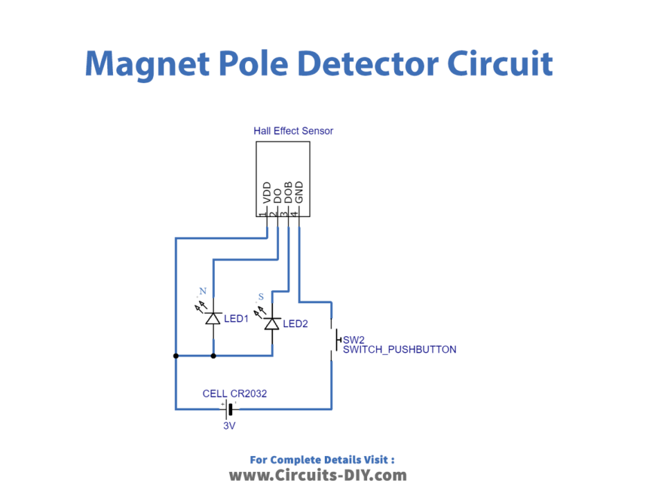
The major component of this circuit is the APX9141 Hall Effect sensor. It has a Hall element and two distinct outputs, DO and DOB, and by utilizing these outputs, we can quickly find the magnet’s poles.
What is Magnet Polarity Detector?
A magnet polarity detector is an electronic sensor that is usually used to detect the two polarities/poles of the magnet. Hence, It integrates a hall effect sensor for that purpose.
Hardware Required
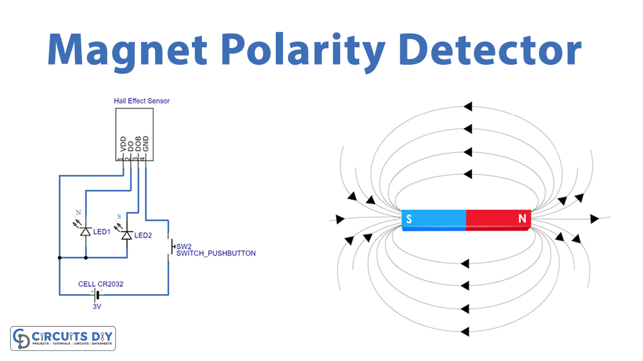
Circuit Diagram
Time to Test
Connect the circuit as described in the above figure, then power the system with a battery. Move a magnet closer to the Magnet sensor; if you bring the south pole close to the DO pin, the Red LED will turn off since the south pole symbolizes the south pole. Similarly, the blue LED (BOB pin )depicts the north pole.
Working Explanation
The APX9141 is a Hall Effect Sensor that is used in this circuit. A Hall Effect sensor is a microelectromechanical systems (MEMS) device that detects and measures magnetic fields on a tiny scale. When the magnetic flux density surrounding the sensor changes due to the magnet, the sensor detects it and creates an output voltage and the LED that is connected to the Magnet sensor changes its state from low to high as a result of this output voltage.
Applicattion and uses
- DC brushless motor applications