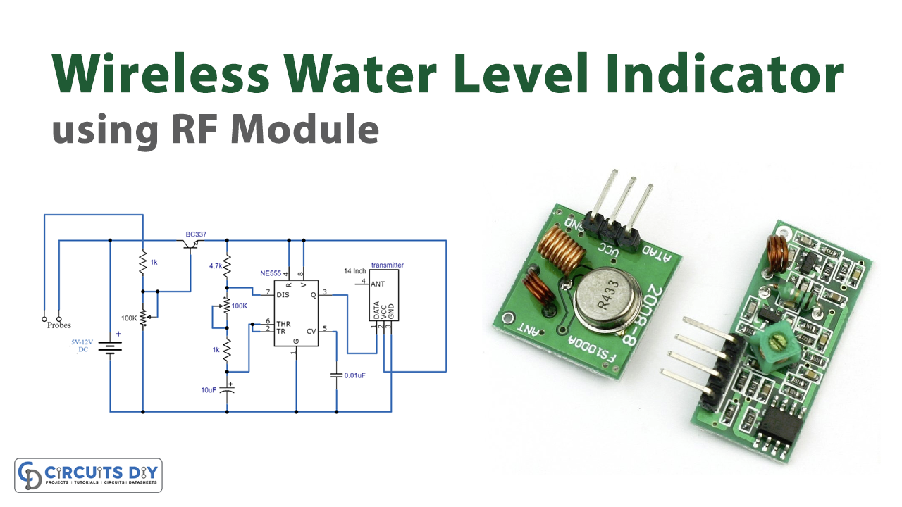
Nowadays water shortage has become an alarming and common problem and the main reason that causes water shortage is the wastage of water. We usually forget to turn the tap off while filling our tanks or any other container so that is another problem we face. But all these issues can be solved with the help of this tutorial. In this tutorial, we are making a project of a Wireless water level indicator using an RF module.
RF module is a device that is used in electronic circuits to transmit and/or receive radio signals between two devices. We are using a readymade RF module in this circuit that is easily available in local electronic markets. This circuit is a portable wireless water level indicator circuit that indicates the required level of water at a distance of up to 100 meters.

Hardware Components
The following components are required to make Transmitter & Receiver Circuit
| S.no | Component | Value | Qty |
|---|---|---|---|
| 1. | Input Supply DC | 5-12V | 1 |
| 2. | IC | NE555 Timer | 1 |
| 3. | Transistor | BC337 | 1 |
| 4. | Resistor | 1KΩ, 4.7KΩ | 2, 1 |
| 5. | Variable Resistor | 100K | 2 |
| 6. | Electrolytic Capacitor | 10µF | 1 |
| 7. | Ceramic Capacitor | 0.01µF | 1 |
| 8. | Transmitter | – | 1 |
| 9. | Antenna | 14 inches | 1 |
| S.no | Component | Value | Quantity |
|---|---|---|---|
| 1 | Input Supply DC | 5-6V | 1 |
| 2 | Transistor | 2N3904 | 1 |
| 3 | Resistor | 10KΩ | 1 |
| 4 | Receiver | – | 1 |
| 5 | Antenna | 14 inches | 1 |
| 6 | Zener diode | 3V | 1 |
| 7 | Piezo buzzer | – | 1 |
NE555 IC Pinout

For a detailed description of pinout, dimension features, and specifications download the datasheet of 555 Timer
2N3904 Pinout
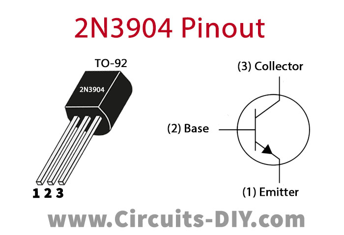
For a detailed description of pinout, dimension features, and specifications download the datasheet of 2N3904
Wireless Water Level Indicator Circuit
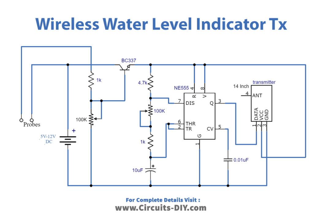
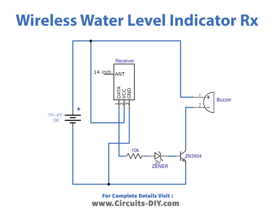
Working Explanation
There are two sections in this circuit one is a transmitter and the other is a receiver. The two probes are used to sense the water, when the water touches these probes it sends a signal to the circuit and the 555 timer IC gets activated and starts producing pulses. These pulses are fed into the transmitter to transmit them into the atmosphere, and they are later received by the receiver in the receiver circuit. they are available at their data pin. A transistor is used to amplify the signal and drive the piezo buzzer. In this way whenever the water reaches the desired level this circuit will indicate to you through a buzzer sound. The sensitivity of this circuit is adjusted by a variable resistor. The maximum distance achieved in the open area is 100m but it’ll be reduced to half i.e. 50m in the area covered by walls and buildings.