A fluorescent lamp is a low-pressure mercury-vapor gas-discharge lamp that uses fluorescence to produce visible light. A typical Fluorescent lamp consists of a glass tube coated with phosphor and containing a pair of electrodes at each end. It is filled with an inert gas typically argon which acts as a conductor and also consists of mercury liquid.
An electric current in the gas excites mercury vapor, which produces short-wave ultraviolet light that then causes a phosphor coating on the inside of the lamp to glow. A fluorescent lamp converts electrical energy into useful light much more efficiently than an incandescent lamp. It gets high popularity to use in a house, as you need to use it with a battery of 6V or 12V without which it cannot light up. Here we design a simple fluorescent lamp driver by using 555 IC and other easily available components.
Hardware Required
| S.no | Component | Value | Qty |
|---|---|---|---|
| 1. | IC | NE555 Timer | 1 |
| 2. | Transistor | BD243C | 1 |
| 3. | Stepdown Transformer | 0-3V | 1 |
| 4. | Resistor | 1.5KΩ | 2 |
| 5. | Variable Resistor | 4.7KΩ | 1 |
| 6. | Capacitor | 100nF | 1 |
| 7. | Connecting Wires | – | – |
| 8. | Fluorescent Lamp | 4 watts | 1 |
| 9. | 12V Battery | – | 1 |
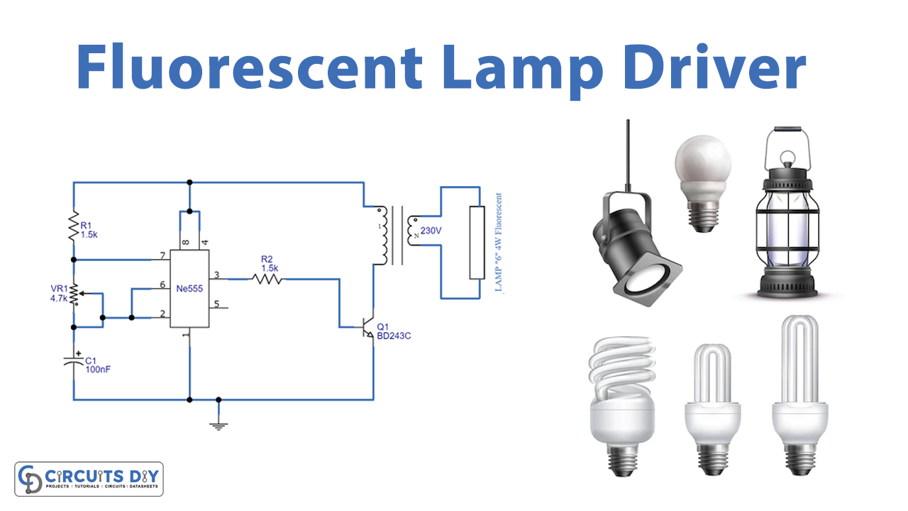
Circuit Diagram

Working Explanation
As we can see in the circuit, the first part includes a NE555 timer IC wired as an astable multivibrator by the timing resistors R1, VR1, and capacitor C1. The output pulses from the IC pin3 are amplified by the transistor Q1. These pulses’ duration can be varied by varying VR1 resistors. Then the transformer steps up the collector voltage to around 1KV to drive the fluorescent lamp.
The transistor BD243C acts as a switching transistor, here stepdown transformer (0-3V) is used to drive 4 watts fluorescent lamp. The lamp is connected at the primary winding, switching circuit is connected at the secondary winding. By the switching pulse EMF is produced at secondary winding this EMF induces primary winding, hence by step-up process high voltage is produced at primary. This is enough to drive a 4-watt fluorescent lamp by connecting the battery and charger circuit we can use it as an emergency light. Before using the circuit, set the VR1 at full resistance and switch on the supply. Now adjust VR1 so that the collector current is 300mA (use a multimeter) and this is the optimum setting for the lamp. Operating the lamp in this setting will give a better life.
Applications
Can be used in kitchens, basements, or garages, where schools and businesses find the cost savings of fluorescent lamps to be significant and rarely use incandescent lights.