Introduction
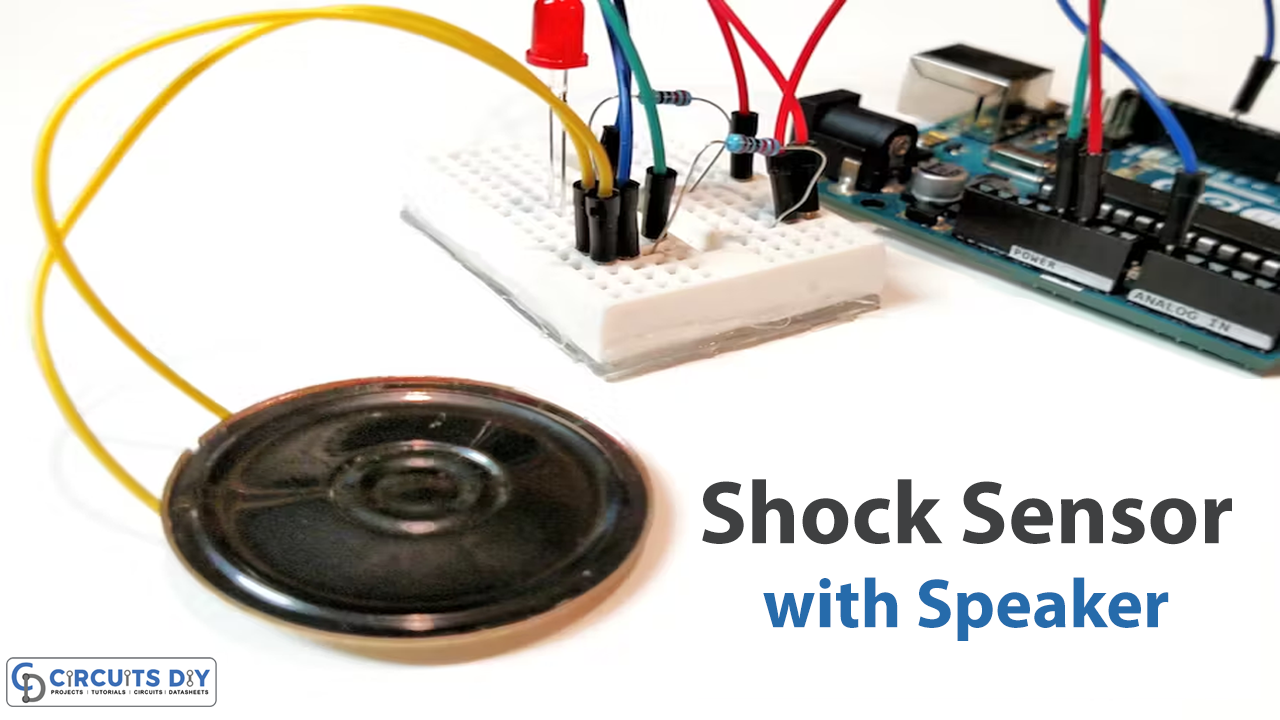
Do you know that with the help of a standard speaker, you can make a sensor? Yes, a shock sensor. In this article, we will be making DIY shock sensors. So, if this caught your eye, read the rest of the article to enhance your understanding of Arduino.
The shock sensor is a key component of a security alarm system. This sensor allows us, as the owners of the cars, to safeguard them against potential intrusion or theft. Shock sensors are typically utilized in vehicle alarm systems, but they may also be used for other purposes, such as protecting homes, enterprises, etc.
What is Shock Sensor
Shock sensors are intrusion detectors that detect human vibrations. In general, the sensors are more effective at detecting break-ins. However, shock sensors have the benefit of being very capable of detecting forced entries. The shock sensor sends signals to activate the feature, such as an alert or a warning message, to the server. It might also be used as an auto-awake feature to turn devices on and off.
Hardware Components
You will require the following hardware for a DIY Shock Sensor.
| S.no | Component | Value | Qty |
|---|---|---|---|
| 1. | Arduino UNO | – | 1 |
| 2. | Speaker 0.25W | 8Ω | 1 |
| 3. | LED | – | 1 |
| 4. | Resistor | 330Ω | 2 |
| 5. | Breadboard | – | 1 |
| 6. | Jumper Wires | – | 1 |
Steps in Making a Shock Sensor
To make this DIY shock sensor, you need to purchase the components listed in the table above. Once you get them all; proceed as follows:
Schematic
Make connections according to the circuit diagram given below.
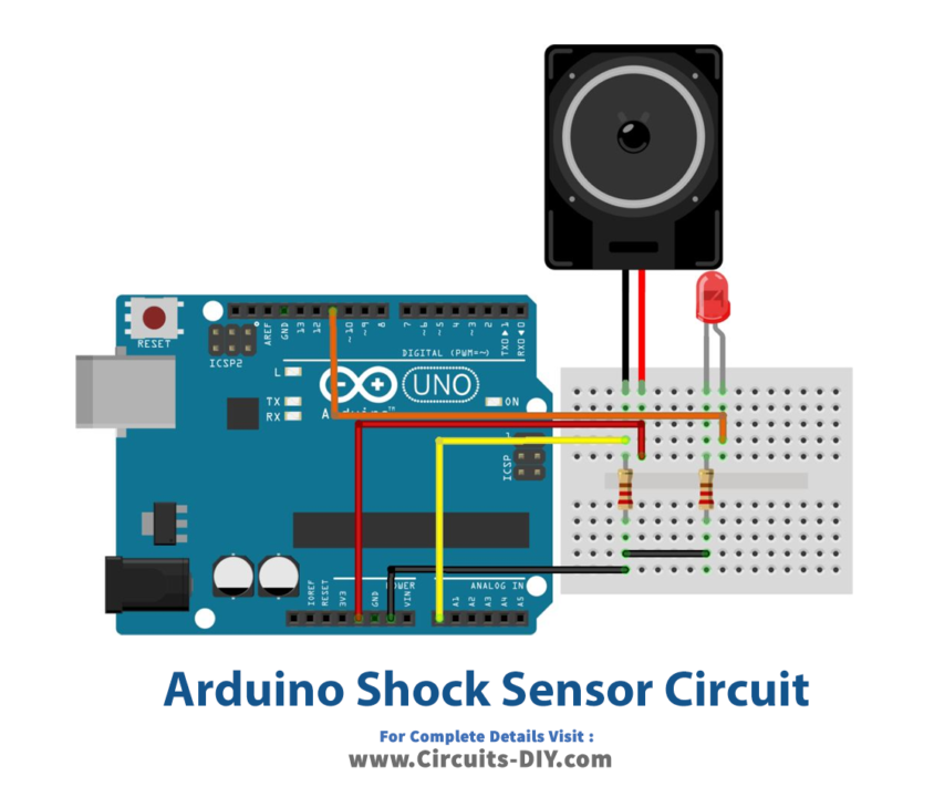
Wiring / Connections
| Arduino | Speaker | Resistor | LED |
|---|---|---|---|
| 5V | +ve | ||
| GND | 1st Pin | -ve with R1 | |
| A0 | -ve | 2nd Pin | |
| D11 | +ve |
Installing Arduino IDE
First, you need to install Arduino IDE Software from its official website Arduino. Here is a simple step-by-step guide on “How to install Arduino IDE“.
Code
Now copy the following code and upload it to Arduino IDE Software.
int shockMin = 996;  //you might need to change these
int shockMax = 1010;  //you might need to change these

void setup() {
  pinMode(11, OUTPUT);
  // Serial.begin(9600); //uncomment this to help with calibration
}

void loop() {
  int shock = analogRead(A0);
  int lightval = map(shock, shockMin, shockMax, 0, 255);
  if (lightval > 0) {
    analogWrite(11, lightval);
  }
  else {
    analogWrite(11, 0);
  }
  // Serial.println(shock); //uncomment this to help with calibration
}
Let’s Test It
It’s now time to test the circuit!
The LED should begin to flicker if you place pressure on the middle of the speaker. If not, the sensor has to be calibrated. To do this, you must perform the following steps:
- On the lines where it says, “//uncomment this to help with calibration,” remove that line
- Open the serial monitor after uploading the code.
- Press the middle of the speaker and observe how the values change.
- Change the low and high values in the serial monitor for the shockMin and shockMax variables
- For instance, if your sensor’s non-pushed state is 500 and its pushed state is 660, alter the shockMax to be somewhere around 700 and the shockMin to be about 480. Next:
- Close the serial monitor.
- Upload the updated code.
- Continue to press firmly on the speaker’s center.
- The LED should now only blink whenever you push the sensor.
Working Explanation
Once you press the sensor, it sends the data to the Arduino via its analog pin A0, which the Arduino will read and transfer information to the output pin. So, if the value is greater than 0, the output pins get high, and so the LED blinks; otherwise, they will remain low.
Applications
- Security alarms
- Car intruder alarms; etc
Conclusion
We hope you have found this DIY Shock Sensor Circuit very useful. If you feel any difficulty in making it feel free to ask anything in the comment section.